XIV.
REPAIRING THE INTAKE AND THE EXHAUST SYSTEMS
Repair the intake and the exhaust systems (the air cleaner, "the air corrector, intake branch pipes,
exhaust pipes and silencers) whenever necessary; inspect them in the course of partial or total
dismantling of the motorcycle and proceed with repairs when the troubles revealed render further
operation of the motorcycle impossible.
XV
REPAIRING THE SIDE-CAR
Proceed with repairing the sidecar when wear of the joints or damage of separate parts and
assemblies are evident.
1. DISMANTLING AND REASSEMBLING THE SIDE-CAR
To detach the side-car body:
- Open the luggage compartment cover and unscrew the top 'fastening nuts of the rubber
members;
- Take the floor carpet out, unscrew the front bolt nuts, which fasten the sidecar body to the
frame, then remove the suspension clips and cushions;
- Remove the sidecar body from the frame;
- Unscrew the bolts of the pressing flange fastening the rubber members and remove the
members (if necessary),
After the required repairs, reassemble the sidecar in the reverse order.
2. REPAIRING THE SIDE-CAR
Repairing the sidecar body.
Repair the side-car body if there are cracks or mechanical damage.
Straighten out all the dented spots, weld up the cracks and dress out the surface. For
reinforcement, some straps may be welded on the inside of the cracked spots. After welding,
straightening out and trimming, touch up the damaged spots with a coat of paint or repaint the
whole body.
Originally grade ÌË-12 enamel is used at the Manufacturing Works for painting, followed by
hot drying.
Repairing the sidecar frame.
Repair the sidecar frame at the time when the motorcycle is
dismantled for repainting, or in case of any defects noticed in service. If after disassembly wear
is found, change broken and/or worn-out parts for new ones.
In case of cracks or damage to the frame proper, weld up the cracks and reinforce the spots with
the aid of stiffeners or cover plates.
XVI
ELECTRICAL EQUIPMENT
1. Wiring and fuses
The electrical equipment of the motorcycle is of the so-called single-wire type, where the
negatives of the sources and users are connected to the “ground” which functions as another
wire. Refer to Table on page
98
for electric diagram. The entire circuit is switched on with the
same ignition lock.
Almost all the circuits are protected through the fuses located under the dashboard on the left
hand motorcycle side. Before replacing the blown fuse, check the reason and fix the fault. Refer
to Table 13 for circuits protected by a specific fuse.
Disconnect the wire from the negative terminal of the battery before repairing the
motorcycle and electric equipment. Never use fuses incompatible with the design and
parameters of the electric system.
88
Summary of Contents for 750cc Series
Page 1: ...Repair Manual 750cc All Models www imz ural com ...
Page 2: ......
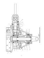
Page 71: ...1 2 3 4 5 6 7 8 Fig 66 Final drive 71 ...
Page 98: ...Fig 11 iring Diagram 9 W 98 ...


