background image

8.

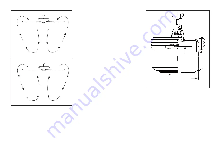
Figure 14

Figure 15

This fan comes with a pre-assembled the blade and front 

guard for your easy installation. Check that all screws are 

tight and securely in place. 

If you need to disassemble the fan for any reason such as 

cleaning, please take off the four guard setscrews and to 

secure the screws after cleaning the blades. (Fig. 16)

Use a lint free lightly damp cloth or duster to remove dust 

from the blades.

Disassembling Your Fan

Figure 16

Screws

Blade

Fan

housing

Front guard

Summary of Contents for UHP9160

Page 1: ...Ceiling Fan Installation Manual UHP9160 UHP9161 ...

Page 2: ...Table of Contents Safety Rules Unpacking Your Fan Installing Your Fan Operating Your Transmitter Care of Your Fan Troubleshooting Specifications 1 2 3 7 9 10 11 ...

Page 3: ...le of reliably supporting a minimum of 35 lbs 15 9 kg or less Use only cUL listed outlet boxes marked FOR FAN SUPPORT 6 The fan must be mounted with a minimum of 7 ft 2 1m clearance from the bottom of the fan guard to the floor 7 Avoid placing objects in the path of the blades 8 To avoid personal injury or damage to the fan and other items be cautious when working around or cleaning the fan 9 Do n...

Page 4: ...n 2 8 Loose parts bag containing a Mounting hardware Wire nuts 3 b Blade attachment hardware Allen wrench 1 Canopy assembly 2 Ball downrod assembly 3 Coupling cover 4 Fan motor assembly 5 Receiver with 6 wire nuts 6 Transmitter incl 2 mounting screws 7 12V MN21 A23 battery 2 1 5 6 3 4 7 8 a b ...

Page 5: ...DUCE THE RISK OF FIRE ELECTRIC SHOCK OR OTHER PERSONAL INJURY MOUNT FAN ONLY TO AN OUTLET BOX MARKED ACCEPTABLE FOR FAN SUPPORT AND USE THE MOUNTING SCREWS PROVIDED WITH THE OUTLET BOX OUTLET BOXES COMMONLY USED FOR THE SUPPORT OF LIGHTING FIXTURES MAY NOT BE ACCEPTABLE FOR FAN SUPPORT AND MAY NEED TO BE REPLACED CONSULT A QUALIFIED ELECTRICIAN IF IN DOUBT Figure 1 Figure 3 Figure 4 Figure 2 Outle...

Page 6: ...over canopy and then through the ball downrod Fig 7 Step 7 Align the holes at the bottom of the downrod with the holes in the collar on top of the motor housing Fig 7 Carefully insert the hanger pin through the holes in the collar and downrod Be careful not to jam the pin against the wiring inside the downrod Insert the locking pin through the hole near the end of the hanger pin until it snaps int...

Page 7: ...the blue light wire to the blue wire from the Receiver Secure wire connections with the plastic wire nuts provided Step 3 Fig 10 Receiver to House Supply Wires Electrical Connections Connect the black hot wire from the ceiling to the black wire marked AC in L from the receiver Connect the white neutral wire from the ceiling to the white wire marked AC in N from the Receiver Secure the wire connect...

Page 8: ...g hole on the mounting bracket secure by tightening the two set screws Note Adjust the canopy screws as necessary until the canopy and canopy cover are snug WARNING Make sure the notch on the hanging bracket properly sits in the groove in the hanger ball before attaching the canopy to the bracket by turning the housing until it drops into place White neutral Green or bare copper ground White AC IN...

Page 9: ...n in Figure 14 This allows you to set your air conditioner on a higher setting without affecting your comfort Cool weather Reverse An upward airflow moves warm air off the ceiling area as shown in Figure 15 This allows you to set your heating unit on a lower setting without affecting your comfort Figure 13 Restore power to ceiling fan and test for proper operation 1 buttons These three buttons are...

Page 10: ...tight and securely in place If you need to disassemble the fan for any reason such as cleaning please take off the four guard setscrews and to secure the screws after cleaning the blades Fig 16 Use a lint free lightly damp cloth or duster to remove dust from the blades Disassembling Your Fan Figure 16 Screws Blade Fan housing Front guard ...

Page 11: ...to avoid scratching the finish The plating is sealed with a lacquer to minimize discoloration or tarnishing Do not use water when cleaning This could damage the motor or the wood or possibly cause an electrical shock 3 You can apply a light coat of furniture polish to the wood blades for additional protection and enhanced beauty Cover small scratches with a light application of shoe polish 4 There...

Page 12: ... housing CAUTION Make sure main power is off 4 Allow a 24 hour breaking in period Most noise associated with a new fan disappear during this time 5 If using an optional light kit make sure the screws securing the lampshade are tight Check that light bulb is also secure 6 Some fan motors are sensitive to signals from solid state variable speed controls If you have installed this type of control cho...

Page 13: ... lbs 37 04 lbs 6 08 Fan Size Speed Volts Amps Watts RPM CFM N W G W C F 23 Low High 120 120 These are approximate measures They do not include Amps and Wattage used by the light kit 0 25 0 31 19 64 37 900 1475 619 17 1008 99 ...

Reviews: