6.
EACH WIRE NUT (WIRE CONNECTOR) SUPPLIED
WITH THIS FAN IS DESIGNED TO ACCEPT UP TO
ONE 12 GAUGE HOUSE WIRE AND TWO WIRES
FROM THIS FAN. IF YOU HAVE LARGER THAN
12 GAUGE HOUSE WIRING OR MORE THAN
ONE HOUSE WIRE TO CONNECT TO THE FAN
WIRING, CONSULT AN ELECTRICIAN FOR THE
PROPER SIZE WIRE NUTS TO USE.
INSTALLATION OF THIS WALL CONTROL
REQUIRES THAT THE THREE-CONDUCTOR
CABLE WITH GROUND WIRE BE RUN BETWEEN
THE CONTROL WALL BOX AND THE CEILING
FAN OUTLET.
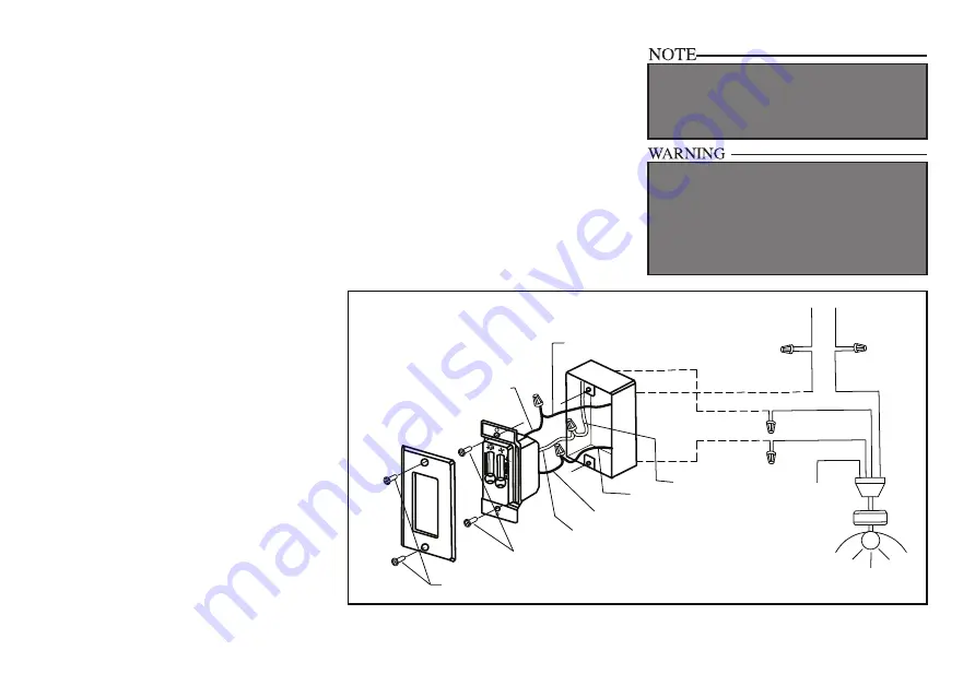
Figure 10
Making the Electrical
Connections
REMEMBER to disconnect the power. If you
feel you do not have enough electrical
wiring knowledge or experience, have your fan
installed by a licensed electrician.
Follow the steps below to connect the fan to
your household wiring. Use the wire
connecting nuts supplied with your fan and
supplied with remote control. Secure the
connectors with electrical tape. Make sure
there are no loose strands or
connections. (Figure 10)
1.
After electricity has been turned off at the
main fuse box or circuit breaker panel,
remove the existing wall plate and switch.
2. Proceed to make the wire connector as
follows (make sure the fan and light slide
switches of the wall control are set in
“OFF” position); Connect the solid Black
wire from the wall control to the Black
with from the fan. Connect the Red or Blue
wire from the wall control to the Blue wire
from the fan. Connect the Black with White
stripes wire from the wall control to the
120V AC hot wire. Use wire connectors
provided to secure the connections.
If your outlet box has a ground wire (green
or bare copper), connect the wall transmitter’s
ground wire to it; otherwise connect the wall
transmitter’s ground wire directly to one of the
screws from the outlet box.
NOTE: Refer to the Schematic on the back
of the wall control.
3.
Secure the UC9031 wall control to the
outlet box using the two 6-32” x 3/4”
screws provided.
4. Secure the face plate over the wall control
with the two 6-32” x 1/4” screws provided.
BLACK / WHITE
RED or BLUE
BLACK
BLACK
RED or BLUE
BLACK / WHITE
RED or BLUE
BLACK
BLUE
BLACK
GREEN
TO
GROUND
WHITE
WHITE
INPUT
BLACK
AC 120V
FAN
(2) #6 - 32 x 1/4” SCREWS
(2) #6 - 32 x 3/4” SCREWS
BLACK / WHITE
Summary of Contents for UHP9210
Page 1: ...UHP9210 UHP9211 UHP9212 ...


