background image

Summer
2019

Assembly Instructions

Round-Top Walk-In Coop

V-M

These written instructions, as 
provided with your purchase, will 
always be the latest iteration of the 
instructions and match the coop 
shipped and provide the most 
complete up-to-date information.

We depend on feedback about our 
instructions to implement changes 
to future versions. Please know 
that we value your input to that 
ongoing process and endeavor to 
produce instructions that are as 
effective as possible for a wide 
variety of customers. 

Copyright ® Urban Coop Company all rights reserved.  

This document is provided to you for your own personal limited use as a paying customer to assemble your coop. We 

consider these instructions company intellectual property and are granting you limited personal use only. Do not copy or distribute without written permission of Urban Coop 
Company. We claim all available Federal protection for the name Round-Top Coop™, our protected designs and trade dress as is allowed by any and all Federal intellectual 
property protection laws. We invest heavily in your coop and work very hard to do a good job and it is only fair that our workers benefit for their hard work.

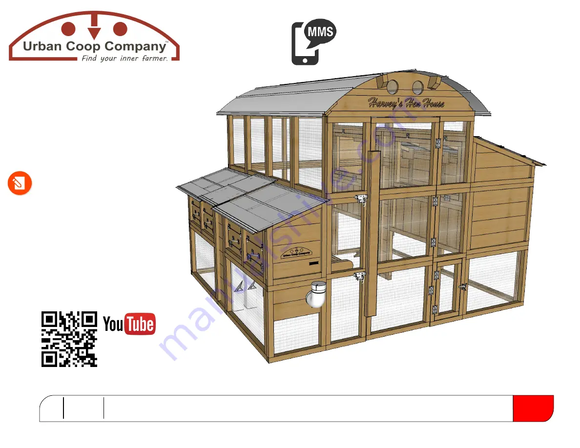
Shown With Optional Waterer & Feeder

Assembly 

Overview...

Use your phones camera to read QR Code.
Representation of procedure... not instructions.

Help Text-line: 

512-596-5200

EMAIL:

 support@urbancoopcompany.com re: Assembly Support

VOICE:

 877-741-COOP | Assembly Support ext 3 

Summary of Contents for Round-TopWalk-InCoop Harvey's Hen House

Page 1: ...mited use as a paying customer to assemble your coop We consider these instructions company intellectual property and are granting you limited personal use only Do not copy or distribute without written permission of Urban Coop Company We claim all available Federal protection for the name Round Top Coop our protected designs and trade dress as is allowed by any and all Federal intellectual proper...

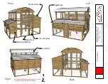
Page 2: ...2019 Copyright Urban Coop Company all rights reserved Orientation Page 01 Front Back Right We recommend having the right side of your coop facing North in weather intense locations Left Roost Area Egg Boxes Run Door Turn Out Door Optional Waterer Run Roof ...

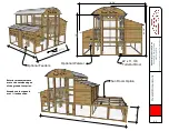
Page 3: ...mpany all rights reserved Overall Dimensions Page 02 99 1 2 27 1 2 110 90 3 4 119 5 8 75 22 x 11 3 8 Turn Out Door Optional Waterer Optional Feeders Sun Room Option 168 25 Exterior measurements are to the outside edges of the ground foot print Ground contact panels are 1 inches wide ...

Page 4: ...d Cedar Our 2x2 s are actually custom milled Wood deemed defective is culled during milling cutting and in fabrication about 5 10 Knots blemishes fraying coloring variations minor surface cracking slight warping and periodic worm marks are normal parts of rough cedar We try to make it to where a reversible part always has a pretty side and take care to make the pretty side show on all parts If you...

Page 5: ...nal determiner of sharp edges A standard metal file from your hardware store or metal snips can be used to make edges to your standards You may choose to wear a pair of work gloves while handling roof metal Be careful not to get caught in coop Children should not play in coop as the doors are not designed to allow easy exit Spending the time up front to identify all the parts and lay them all out ...

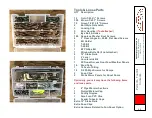
Page 6: ...oor Hinges 24 8 Flat Head Screws 1 Bit Holder 1 T 25 Bit 1 T 20 Bit 1 2 Phillips Bit 1 Window Bolts X8 if not attached 2 12 Stake Nails 1 2 Level 1 Countersink Bit 1 2X Roost Access Door Fowl Weather Panels 10 Brad Nails 1 10 Feet of String 12 5 8 Phillips Screws for Ramps 3 Snap Clips 2 Stock Storm Panels for Roost Doors Optionally your kit may have the following items and loose parts 2 4 Pipe Wa...

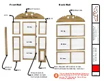
Page 7: ... Door Handle A4 Front Arc D2 Back Arc A3 L A2 L A2 R A3 R A1 Low A1 Mid A1 Up D1 Up D1 Mid D1 Low If you ordered the Double Door Option you will have 2 sets of all A 1 2 3 Wall panels and no D1 Wall panels You will have 2 A5 door handles too Hinge locations pre drilled on right but not pre installed Door shipped with retainer screw latch hardware installed by customer ...

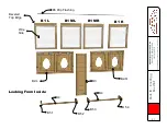
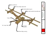
Page 8: ...k In Coop V M July 2019 Copyright Urban Coop Company all rights reserved Parts ID Inner Egg Box Wall Page 07 B6 Drip Flashing B1 L B1 ML B1 MR B1 R B2 L B2 R B3 B4 B4 B 5 1 B 5 2 B 5 3 B 5 4 Wire Side Beveled Top Edge Looking From Inside ...

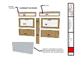
Page 9: ...19 Copyright Urban Coop Company all rights reserved Parts ID Inner Roost Wall Page 08 Looking From Inside Beveled Top Edge C5 C4 C1 C1 C2 C2 C3 C3 Wire side 2 Stock CoroClear storm panels with magnets installed to offer wind protection for C2L and C2R panels ...

Page 10: ...alk In Coop V M July 2019 Copyright Urban Coop Company all rights reserved Parts ID Run Roof Parts Page 09 E2 Roof Supports 2X E3 Eaves Magnet Magnet 2 Sets of 3 Beveled Top Edges 3X E5 Galvalume Roof Metal Panels 107 57 7 8 E1 Mid Arc ...

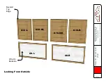
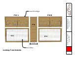
Page 11: ...ctions Round Top Walk In Coop V M July 2019 Copyright Urban Coop Company all rights reserved Parts ID Roost Outer Wall Page 10 Looking From Outside Wire On Backside Beveled Top Edge G10 L G10 ML G10 MR G10 R G9 L G9 R ...

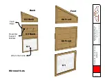
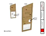
Page 12: ...p Walk In Coop V M July 2019 Copyright Urban Coop Company all rights reserved Parts ID Roost Front Back Page 11 Mirrored Sets G2 Front G2 Back G3 Front G3 Back G1 G1 Front Back Wire to the Inside Roost Bar Support Bracket Flush Edge ...

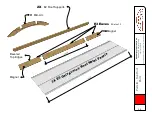
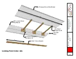
Page 13: ...019 Copyright Urban Coop Company all rights reserved Parts ID Roost Roof Parts Page 12 G15 Upper Roost Roof Metal G15 Lower Roost Roof Metal Trimmed Edge 3X G11 Eave Boards 33 1 2 103 G12 Roof Supports 3X G13 Roof Support Brackets 3X Looking From Under side ...

Page 14: ...July 2019 Copyright Urban Coop Company all rights reserved Parts ID Roost Parts Page 13 G4 Roost Bars 4X G7 Roost Ramp Supports 2X G14 Mid Roost Bar Support Bracket G8 Mid Roost Bar Support G6 Roost Ramp Landing G5 Longer Ramp G5 Upper Ramp 2X Hinges ...

Page 15: ...tructions Round Top Walk In Coop V M July 2019 Copyright Urban Coop Company all rights reserved Parts ID Egg Box Outer Wall Page 14 Looking From Outside Wire to Back F10 L F10 R Beveled Top Edges F12 F11 F11 12 1 2 ...

Page 16: ...Instructions Round Top Walk In Coop V M July 2019 Copyright Urban Coop Company all rights reserved Parts ID Egg Box Front Back Page 15 Wire Side In Back Front Mirrored Parts F2 F2 F1 F1 Hole For Optional Waterer ...

Page 17: ... Top Walk In Coop V M July 2019 Copyright Urban Coop Company all rights reserved Parts ID Egg Box Inner Parts Page 16 Magnets F7 Inner Dividers F7 F6 F6 Outer Dividers F8 Egg Box Floor F8 F9 F9 Feeder Bracket For Optional Feeders ...

Page 18: ...In Coop V M July 2019 Copyright Urban Coop Company all rights reserved Parts ID Egg Box Roof Parts Page 17 Lipped Edge Lipped Edge F15 Left Eggbox Roof F15 Right Eggbox Roof F16 Feeder Area Roof Magnet F14 Eave F13 Eave Beveled Edge 44 18 ...

Page 19: ...und Top Walk In Coop V M July 2019 Copyright Urban Coop Company all rights reserved Parts ID Feeders Waterer Page 18 F3 Optional Feeders F5 Waterer Brackets F4 Optional Waterer delivered in 2 sections Standard Poultry Nipples ...

Page 20: ...stration of what you ll end up with after that section is complete Not our quote but we like it Showing back side of finished run as if you ordered the double door option Front and back would be the same If you did not order double door kit it will be solid as illustrated in the following section Must be built on level ground Finished coop will weigh 800 pounds and is not designed to be moved Sect...

Page 21: ...oles Screw Into B3 From Frames of B2 s Flush Flush If you bought double door kit there are no D panels Build another A panel wall just like in front on back too step 4 See previous page for illustration Included Included Included Green arrows indicate a Brown T25 Screw and its direction Wire Side In Wire Side In Put Screws Up From Bottom D1 Mid D1 Low B2L B2R B3 A2L Flush Tops Front Back order of ...

Page 22: ...k Front Bottom Edge C1L Lines Up To Seam Between D Panels about 25 inches up from bottom Open Doors To Access Screw Holes Swing Inward 3 6 C4 C5 C2 L C2 R C1 L C1 R 2 5 4 1 Wire In A2R Same On Front And Back 7 Using provided level check what you have built so far on all side and adjust soil and contact points as needed No D Wall If You Have Double Door Option ...

Page 23: ...Page 22 Back 4 B1L Bevel Slant Out B1ML B1MR B1R Z Flashing Tack In Using 6 8 Provided Brad Nails Centered L to R D1 Upper Panel A3L Front 3 1 2 1 If you don t see screw holes check other side of board If we goofed up and missed a hole we include a drill bit Wire Facing In All B1 s Open Doors For Screws Access These Screws From Other Side ...

Page 24: ...uly 2019 Copyright Urban Coop Company all rights reserved Step 1D Upper Run Roost Side Page 23 Back 4 C3 R Front 3 1 2 Bevel Out C3 L A3 R Open C2 Doors to Access Screws C2 R C2 L D1 Top Wire Side Wire Facing In Access These Two Screws From Other Side ...

Page 25: ...e 24 Back Front 3 1 2 Edges Flush Tap Into Place E2 Roof Supports Lock into notches A4 Front Arc D2 back arc screw in up from D1 top Wire Side E1 4 After installing E2 supports slide up E1 mid roof support from bottom centered and affix to underside of E2 supports with screws Fit best way its reversible Use 2 of the Long E4 Gold Screws ...

Page 26: ... up and is critical for remainder of steps 4 Door Side Stakes Adjust Door Width Open Turn Out Door to Access Right Stake Hole Hammer Door Stakes Into Pre Drilled Holes To Pin Door Width Into Place Use your measuring tape in step 1 Use your hammer 3 Using provided level double check top edges Should be pretty close Move adjust as needed After this step coop will become too heavy to move and level A...

Page 27: ...Is Centered Use Bit Holder No Bit Magnet Helps Hold Roof While Installing 3 Over Hang Outer E3 s Have Magnets 1 B1 B1 B1 B1 Screw Into Top Edge of B1 s Eave Boards Repeat other side 2 3 4 5 6 Top Panel Holes Both Edges Lower Panels Holes on Bottom Edge Center Left to Right Roof Edge Overhangs Eaves by 2 inches Edge with extra lip faces out Roof Overhangs Ends By 1 inch Top Edge Of Lower Roof Panel...

Page 28: ...me of coop purchase After completing assembly reference Sun Room Addendum instructions Section 2 Instructions going forward will omit some complexity as HOPEFULLY we did a good job laying some common foundations and you are catching on to the techniques and our lingo You can always call our support hotline at 877 741 2667 or text your questions and photos to 512 596 5200 Standard Coop View ...

Page 29: ...Side Sub Assembly Page 28 G2 3 2 1 G1 G3 G9 G9 G10L G10ML G10MR G10R Overhangs About Each End Install center G11 eave first Then outer eaves Beveled edge to top Flush with edges of G10 s See Next Page If You Ordered Sunroom Option 4 5 6 5 Repeat Back Side Repeat Back Side Wire Out Beveled Edge Flush Overhang Bottoms Flush ...

Page 30: ...mpany all rights reserved Step 2A1 Roost Side Sun Room Support Page 29 Front Skip Page If You Did Not Order Sunroom Option Support panel in place of G9 s G9 s will get used in Sunroom Centered See Sun Room instructions addendum for additional details to be completed after this packet ...

Page 31: ... side roost wall Illustrated without the sunroom support panel for remainder of instructions until end when actual optional sunroom instructions are addressed 41 3 4 Center at 41 3 4 to top of G14 Bracket 21 7 8 21 7 8 G13 Bracket Centered 1 T 20 Torx Don t over drive screws or they may stick out back side Measured to center of cut out on bracket Brackets flush with slant of eaves Top Edges Flush ...

Page 32: ...roost roof supports in to place and secure into place as illustrated in Fig 1 Trimmed Edge Under Top edge of upper roof panel jambs up against coop wall lays over top of lower roof panel 2 Roof Screw 3 Roof screws along edges and on supports into pre drilled holes Tighten only enough to compress rubber washer 3 G12 Supports 2 G15 Roof Panels 103 Lip Out ...

Page 33: ...for clarity Install through roost access doors or from inside if you re smaller Place roost bars with notches towards outside Place G7 Roost Ramp Supports In Roost Bar Notches 5 E5 Screw G6 roost ramp landing Screw in from front and back sides Attach G5 ramp shorter ones to G7 support with provided E5 screws Repeat other side Attach G5 Longer ramp to G6 platform with E5 screws Either side is fine ...

Page 34: ...Assembly Instructions Round Top Walk In Coop V M July 2019 Copyright Urban Coop Company all rights reserved Section 3 Eggbox Assembly Page 33 ...

Page 35: ... F12 F11L F11R F1 Screws on this end same as other end Lower F1 panel is all wire Front F1 has water cutout Attach bottom panel to front and make flush on bottom Attach mid panel and make flush on bottom Attach bottom and back panels Attach left and right door panels Attach front back F2 panels Cutout for optional waterer Flush Flush Bottoms Drop doors to access screw holes ...

Page 36: ...ing egg box sub assembly Bottom edge of brackets flush with door frame and door side Bar captured between brackets Use 8 of the E4 Gold GRK Screws 1 2 3 4 Brackets are labeled for positions as indicated 4 B5 Jump Bar brackets 2 B4 Bars same E4 screws from back side two for each bracket X X X X X Screw in 4 eye hooks where indicated Cup hooks can hold open doors when hooked into the wire panels abo...

Page 37: ...or Page 36 Install egg box floors into sub assembly before attaching to coop Install Flush With Bottom F2 Wire Facing Down F8 F8 F9 Edge With Wire On This Side Screw on from sides and back 1 2 3 Back edge of floor installs flush with bottom board of egg box door panels screws in from outside All this row of screws from outside ...

Page 38: ...agnets Slide dividers downward Tap into place if needed Bottom out to the floor Carefully slide egg box sub assembly into place and attach on both ends 2 F6 F6 F6 F6 After all F6 dividers are in place secure from both sides into F10 B2 3 F10 F10 B2 B2 Gently tap upper F9 into center area wire side down to inside about 4 inches down and level Ledge boards of both inner F6 dividers face outwards 4 ...

Page 39: ...es for nipples are aligned Tip smear glue evenly only on the male section insert and turn a little to aligned position 2 Taller feeders Shorter feeders 3 Insert feeders After glue is dried insert water tube into the position shown and have someone hold in place 4 Egg box center support Attach both F5 support brackets from bottom into center support of egg box floor to where it hangs waterer in a l...

Page 40: ...s feeders and is held in place by magnets Fold to inside on F15 s F14 F13 Force up against edge of coop Screw in place with back edge flush the 2 F13 outer eave boards and the center F14 eave board Make sure magnets in F14 face up 1 Screw down both F15 outer roof panels with lip to the inside using roof screws as indicated 2 F15 F15 F16 Lipped Edge Out ...

Page 41: ...sides Align A5 handle where top hole is in middle A5 Handle Door handle screws to left side of door frame from back using pre drilled holes Handle Screws In from back side of door Large Pan Head Screw Use large pan head screws to install both H5 Latches where they slide freely 2 Install hinges in predrilled holes using flat head Philips screws 3 4 Flat Head Screw Bit Small Pan Head Screw Using sma...

Page 42: ...uard Nipples If you have the optional Freeze Guard Nipples they must be removed to completely remove the waterer Digging Predators Due to varied terrain around the country we do not propose only one method of protecting from digging predators Call if you have questions and we can help you decide on the best method if it is something you are concerned about If You Ordered The Feeders Feed may clog ...

Reviews: