background image

MRF-260 B

ASE

S

TATION

Page 8

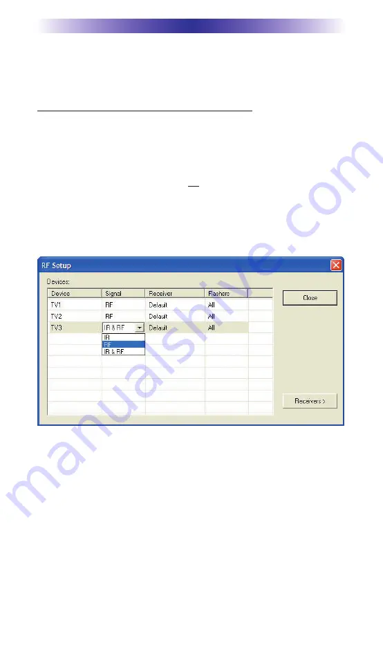
By looking at the Signal column, you can see that the factory
default programming sets all of the devices to send both IR and RF
commands.  If you look at the column for Flashers, you can see that
the default sends IR commands for all devices to ALL of the flash-
ers. Both options must be changed for identical components.
Additionally, you must disable the Front Blaster (see page 6 for
directions).

Step 3 - Adjust the Signal For Each of the Identical Devices

The RF Setup window enables you to adjust the Signal output for
each device individually, by clicking on the intersection of a row
and a column and then selecting RF from the three options shown
in the pull down list box.

Select RF from the three options shown for EACH of the identical
TVs. You may leave the other components of the system set to IR
& RF.

Step 4 - Adjust the Flashers For Each of the Identical Devices

The RF Setup window enables you to adjust which Flashers output
by the remote control for each device individually, by clicking on
the intersection of a row and a column and then selecting 

1-4 

from

the seven options shown in the pull down list box. 

Select the correct Flasher (refer to your connection notes) for
EACH of the identical TVs. You may leave the other components of
the system set to ALL.

See figure on the next page.

Summary of Contents for Complete Control MRF-260

Page 1: ...Order Number GETEC C1 09 183 FCC Class B Class II Permissive Change Test Report Number GETEC E3 09 099 Page 1 1 EUT Type Base Station FCC ID OZ5URCMRF260 APPENDIX H USER S MANUAL ...

Page 2: ...MRF 260 Installation Manual Optimizing Narrow Band Reception with Complete Control Remotes ...

Page 3: ...OR EDITORIAL ERRORS OMISSIONS MADE IN THIS MANUAL The Home Theater installation on the cover was designed and installed by Stone Glidden of King of Prussia and Doylestown PA The information in this manual may be subject to change without prior notice Complete Control is a registered trademark of Universal Remote Control Inc All other brand or product names are trademarks or registered trademarks o...

Page 4: ...ront Blaster Overload 6 Disabling the Front Blaster Step by Step via PC 6 Controlling Four Identical Components Zones 7 Identical Components Zones Step by Step via PC 7 Programming For Multiple Equipment Locations 10 USA Limited Warranty Statement 11 Frequently Asked Questions 12 Specifications 12 ...

Page 5: ...50 or MX 350 remote controls manufactured before November 1 2006 or an MX 3000 built before April 2005 You can identify the build date of a remote control by looking at the serial number The first 6 digits indicate the build date If the serial number appears as 122905 014054 the first 6 digits indicate that the remote was built on December 29 2005 2 The MRF 260 s integrated Narrow Band RF receiver...

Page 6: ...med to specifically control components in a particular room by installing an MRF 260 base station at each location In operation it s simple when you select a device located in the Den the MX TX remote only sends commands to the Den When you select a device located in the Family Room the MX TX remote only sends commands to it A Single MRF 260 Can Control an Array of Identical Components or Identica...

Page 7: ...cable boxes HDTV tuners DVRs PCs or any other device with a high speed micro processor these generate broad band Radio Frequency Interference RFI Of course you should keep in mind that the emitter cables are 10 long MRF 260 BASE STATION Check that the arrow pointer in the center of the wheel is pointed to 0 the default interference sniffing position If it is not use a small flat blade screwdriver ...

Page 8: ... a valid RF ID Watch the Status LED on MRF 260 it should light every time you press a button on the remote This confirms that the signal was received and understood perfectly If you repeat any button press multiple times and the Status LED lights correctly every time you have no interference and a very reliable installation If some of the presses do not light the Status LED you still have some RFI...

Page 9: ... remote control is set to a particular LINE OUT rather than ALL When IR commands are sent to all the flashers in a cabinet you can have difficulty adjusting the IR Output Reprogram the remote control to send IR commands only via a specific 1 4 Line Output then readjust the IR Line Output level Note Remember the MRF 260 will NOT respond if you select IR line outputs 5 or 6 The MRF 260 has only four...

Page 10: ...ade to an MRF 350 Disabling the Front Blaster Step by Step via PC Note If you are programming a URC MX addressable remote control that sets up without a PC refer to the owners manual to dis able the Front Blaster Open the PC software then plug the MX PC programmable remote control into the PC Open your saved configuration and follow these steps to turn off the front blaster Step 1 Open the RF Setu...

Page 11: ...e SIGNAL of the remote should be set to RF ONLY for each identical component IR can still be utilized for other devices in your system 3 You must note the NUMBER of the Flasher Output you have uti lized for EACH of the identical components Identical Components Zones Step by Step via PC Step 1 Create and Program a Device for Each Component Zone Try to name each device with a descriptive title At a ...

Page 12: ...ndividually by clicking on the intersection of a row and a column and then selecting RF from the three options shown in the pull down list box Select RF from the three options shown for EACH of the identical TVs You may leave the other components of the system set to IR RF Step 4 Adjust the Flashers For Each of the Identical Devices The RF Setup window enables you to adjust which Flashers output b...

Page 13: ... to selections 1 through 4 Step 5 Make sure that the ID is set on both the remote and on the wheel of the MRF 260 Click on the Receivers button and set the RF address to one of the first 15 addresses 1 9 or A B C D or E The second set of address es is only supported by MSC units Step 6 Close the RF window and Download to the Remote ...

Page 14: ... Extend the RF Setup window by clicking on the Receivers button of the RF setup window Step 3 Add Name and Assign Receiver ID Using the controls at the bottom extended portion of the RF Control window add new receivers and rename them for the equipment location Step 4 Save and Download to your remote You may rename the Default receiver to something more descriptive by clicking on the Rename button...

Page 15: ...ogramming artwork software or other materials that may have been programmed into your unit It is likely that such data software or other materials will be lost during service and Universal Remote Control will not be responsible for any such damage or loss A dated purchase receipt Bill of Sale Installation Contract or other verifiable Proof of Purchase is required For product support and other impo...

Page 16: ... panel blaster by setting the device to a specific IR Line Output instead of ALL then adjust the Line Output I have a row of identical TVs I ve correctly set the flasher outputs using the Editor software yet when I send a command to one of them the TV next to the selected TV also responds How do I stop this First check the RF ID if the RF ID is set to 0 IR routing does not work Second set the RF I...

Page 17: ... harmful interference to radio or television reception which can be determined by turning the equipment off and on the user is encouraged to try to correct the interference by one more of the following measures Reorient or relocate the receiving antenna Increase the separation between the equipment and receiver Connect the equipment into an outlet on a circuit dif ferent from that to which the rec...

Reviews: