background image

Page 10

MRX-2 N

ETWORK

B

ASE

S

TATION

Federal Communication Commission
Interference Statement

This equipment has been tested and found to comply with the limits for a
Class B digital device, pursuant to part 15 of the FCC Rules. These limits are
designed to provide reasonable protection against harmful interference in a
residential installation. This equipment generates, uses and can radiate radio
frequency energy and, if not installed and used in accordance with the instruc-
tions, may cause harmful interference to radio communications. However,
there is no guarantee that interference will not occur in a particular installa-
tion. If this equipment does cause harmful interference to radio or television
reception, which can be determined by turning the equipment off and on, the
user is encouraged to try to correct the interference by one more of the follow-
ing measures:

u

Reorient or relocate the receiving antenna.

u

Increase the separation between the equipment and receiver.

u

Connect the equipment into an outlet on a circuit different from
that to which the receiver is connected.

u

Consult the dealer or an experienced radio/TV technician for
help.

Warning!

Changes or modifications not expressly approved by the manufacturer could
void the user's authority to operate the equipment.

Note : The manufacturer is not responsible for any Radio or TV interference
caused by unauthorized modifications to this equipment. Such modifications
could void the user's authority to operate the equipment.

FCC Caution

This device complies with Part 15 of the FCC Rules. Operation is subject to the
following two conditions: (1) this device may not cause harmful interference,
and (2) this device must accept any interference received, including interference
that may cause undesired operation.

Any changes or modifications not expressly approved by the party responsible
for compliance could void the authority to operate equipment.

Summary of Contents for MRX-2

Page 1: ...MRX 2 Owner s Manual Network Base Station ...

Page 2: ...CONTROL INC SHALL NOT BE LIABLE FOR OPERATIONAL TECHNICAL OR EDITORIAL ERRORS OMISSIONS MADE IN THIS MANUAL The information in this manual may be subject to change without prior notice Complete Control is a registered trademark of Universal Remote Control Inc All other brand or product names are trademarks or registered trademarks of their respective companies or organizations 500 Mamaroneck Avenu...

Page 3: ...Features and Benefits 2 Parts Guide 3 Front and Rear Panel Descriptions 4 Network Installation 6 Specifications 7 USA Limited Warranty Statement 8 Federal Communication Commission Interference Statement 10 Declaration of Conformity 11 ...

Page 4: ...iple MRX 2 s Control equipment such as shades and TV lifts using the base stations sensors relays and RS 232 ports Control URC RF Lighting using the optional RFTX 1 transmitter When used in a Complete Control System The MRX 2 is required to use the CC Control App for iOS devices like the iPad and iPhone Extend control to other rooms by installing multiple MRX 2 s throughout the home or commercial ...

Page 5: ...control or iOS device When used in a Complete Control System Enables iOS Control The addition of an MRX 2 base station to a control system allows for control via URC s CC Control iOS app for iPads iPhones and iPod touch Each iDevice requires programming by a qualified custom install professional Note Requires the purchase of CC Control Setup code one code per system No Aiming Using a base station ...

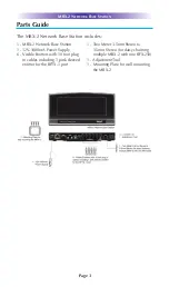
Page 6: ...work Base Station 1 12V 1000mA Power Supply 6 Visible Emitters with 10 foot plug in cables including 1 pink sleeved emitter for the RFTX 1 port 1 Two Meter 3 5mm Stereo to 3 5mm Stereo for daisy chaining multiple MRX 2 with one RFX 250 1 Adjustment Tool 1 Mounting Plate for wall mounting the MRX 2 ...

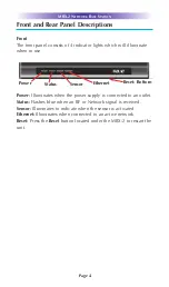
Page 7: ...pply is connected to an outlet Status Flashes blue when an RF or Network signal is received Sensor Illuminates to indicate when the sensor is activated Ethernet Illuminates when connected to an active network Reset Press the Reset button located under the MRX 2 to restart the unit Power Status Sensor Ethernet Reset Bottom MRX 2 NETWORK BASE STATION Page 4 ...

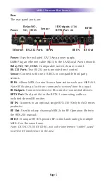
Page 8: ...t IR Outputs Connect emitters for IR control of connected devices RFTX Port Dual port 6 for the RFTX 1 connecting cable or included sleeved IR emitter RF IN Connects to an optional single RFX 250 Only for MX series products RF Out Used for daisy chaining MRX 2s for RF Operation Refer to the RFX 250 manual RF ID 15 unique RF ID s provide RF control and routing to multiple MRX 2 s in the same home N...

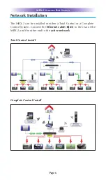
Page 9: ...rk Installation The MRX 2 can be installed in either a Total Control or a Complete Control System Connect the Ethernet cable RJ45 to the rear of the MRX 2 and the other end to the active network Total Control Install Complete Control Install ...

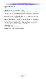
Page 10: ...via URC sensors RS 232 Two RS 232 ports support TX RX and GND two way communication via URC cables IR Six adjustable IR ports enable the included URC emitters to control IR devices Note 6th IR Output requires the included sleeved emitter identified by a pink connector since it can optionally be used to connect an RFTX 1 Weight 8 4 oz Size 248 x 120mm x28mm Power 12V External Power Supply ...

Page 11: ...ackup any macro programming artwork software or other materials that may have been programmed into your unit It is likely that such data software or other materials will be lost during service and Universal Remote Control will not be responsible for any such damage or loss A dated purchase receipt Bill of Sale Installation Contract or other verifiable Proof of Purchase is required For product supp...

Page 12: ...ISING OUT OF OR IN CONNECTION WITH THE ABILITY OR INABILITY TO USE THE PRODUCTS ACCESSORIES OR SOFTWARE TO THE FULL EXTENT THESE DAMAGES MAY BE DISCLAIMED BY LAW EXCEPT TO THE EXTENT PROHIBITED BY APPLICABLE LAW THERE IS NO OTHER WARRANTY EXPRESSED OR IMPLIED UNIVERSAL REMOTE CONTROL WILL NOT BE HELD RESPONSIBLE FOR STATE MENTS MADE BY OTHERS CONCERNING THE MERCHANTABILITY OR FITNESS FOR A PARTICU...

Page 13: ...ow ing measures u Reorient or relocate the receiving antenna u Increase the separation between the equipment and receiver u Connect the equipment into an outlet on a circuit different from that to which the receiver is connected u Consult the dealer or an experienced radio TV technician for help Warning Changes or modifications not expressly approved by the manufacturer could void the user s autho...

Page 14: ...ith the requirements of EMC Directive 2004 108 EC issued by the Commission of the European Community Compliance with these directives implies conformity to the following European Community n EMC Directive l EN 55022 l EN 55024 l EN 61000 3 2 l EN 61000 3 3 List of test reports and or certificate verified compliance with the standards above Date of issue January 30 2013 Name and signature of author...

Page 15: ......

Page 16: ...500 Mamaroneck Avenue Harrison NY 10528 Phone 914 835 4484 Fax 914 835 4532 www universalremote com OCE 0076D Rev 01 ...

Reviews: