25
DS1375-020E
11.6.1 CONNECTION OF 1375/821 – 1375/822 EXTERNAL IP VIDEO STATIONS
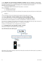
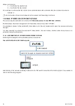
Following is the diagram of the possible system connections:
Use with PoE Switch with VLAN support.
iPerTAlk
VLAN 5 (tagged)
PoE Switch Managed with VLAN Support Ref. 1375/702
VLAN 5
(untagged)
1375/821
1375/822
Alternatively, if the network is already made with non-PoE switch and without the VLAN support, it is possible to
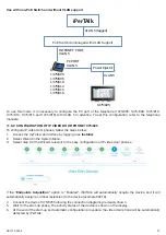
refer to the following diagram:
Use with non-PoE Switch and without VLAN support
iPerTAlk
VLAN 5
PoE Switch Unmanaged with VLAN Support
VLAN 5
1375/821
1375/822
INTERNET PORT
VLAN 5
1375/805
1375/806
1375/810
1375/812
1375/815
1375/816
PC PORT
Power Iniector
To use this mode, it is necessary to configure in advance the PC port of the telephone (Ref. 1375/805, 1375/810,
1375/812, 1375/815 and 1375/816) with VLAN 5. To set this configuration, refer to the telephone manuals.13
Summary of Contents for iPerTAlk 1375
Page 98: ...98 DS1375 020E...
Page 99: ...99 DS1375 020E...


