40
DS1375-020E
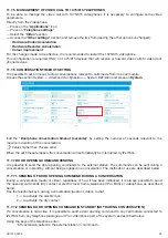
11.8.3 CONFIGURATION OF SWITCHBOARD CALL (MAIN TELEPHONE)
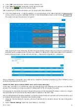
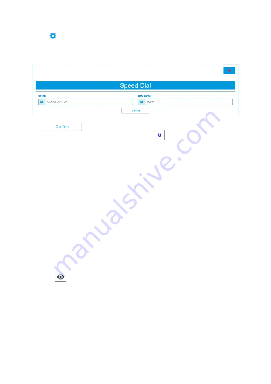
To configure the switchboard call on the video door phone Ref. 1375/825 access the System section and press
on
Speed Dial
.
Press on the key
and enter the following parameters:
— In the “
Called
” field, enter the “ SWITCHBOARDC” parameter.
— In the “
New target
” field, enter the extension number of the device to be used as switchboard.
WARNING!
It is not possible to configure a video telephone terminal as a switchboard (main telephone).
Press the key
to make the configuration operative.
On all the video door phones present on the system, press the key
to be able to make a call to the switchboard.
11.8.4 MAKING A CALL FROM VIDEO DOOR PHONE TO TELEPHONE OR VIDEO DOOR PHONE
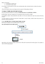
To make a call from video door phone 1375/825 just search for the contact to call in the phonebook. The video
door phone will automatically start the call to the device associated with the destination telephone number.
The destination telephone or video door phone will receive a standard call coming from the extension associated
to the video door phone which is calling.
WARNING!
It is not possible to make a call to a video telephone terminal.
For more details, see the User’s manual supplied with the IP video door phone.
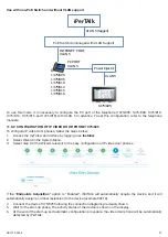
11.8.5 MAKING A CALL FROM TELEPHONE TO VIDEO DOOR PHONE
To make a call from a telephone (PC or BCA) to the IP video door phone just dial the extension number associated
with the video door phone (e.g. 203). The system will automatically make a call to the device.
WARNING!
It is not possible to make a call from a videophone to a video door phone Ref. 1375/825.
11.9 AUTOMATIC ACTIVATION FROM IP VIDEO DOOR PHONE 1375/825 OR FROM
VIDEOPHONE 1375/815 AND 1375/816
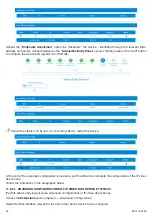
When IP video door phone 1375/825 or videophone 1375/815 are in standby, it is possible to perform the automatic
activation.
This function allows displaying on the video door phone or on the videophone images taken from the external
station.
— Press the button
on the device 1375/825, then select the external station.
— It is necessary to dial the number of the extension associated with the external station on the device 1375/815
and 1375/816.
WARNING! performing the automatic activation from videophone 1375/815 and 1375/816will automatically
activate also the audio channel, besides the video one, and the LEDs of the external station camera will
light up.
For more details, see the User’s manual supplied with the IP video door phone Ref. 1375/825 or videophone
1375/815 and /816.
11.10 ACCESS CONTROL (ADMINISTRATOR USER ONLY)
The iPerTAlk system integrates the access control service, which allows the opening of access points (doors,
gates, bars, etc.) through the insertion of Door Codes. To control the access point opening, it is possible to use
Call modules 1375/823 and 1375/824 (colour). Call modules feature a keypad allowing to enter a code.
Summary of Contents for iPerTAlk 1375
Page 98: ...98 DS1375 020E...
Page 99: ...99 DS1375 020E...


