18
CAUTION: Unusual noise or vibration indi-
cates a problem. Do not continue to operate
until you identify and correct the source of the
problem.
COMPRESSOR CONTROLS
ADJUSTMENT PROCEDURE. Select either auto-
matic start and stop control or constant speed
control by adjusting the knob on the auxiliary
valve. For automatic start and stop control,
turn the knob on the auxiliary valve fully clock-
wise to disable the auxiliary valve. The pressure
switch will then start and stop the unit.
NOTE: For dual control models, automatic start
and stop is preferred.
CAUTION: Running unloaded for more
than 20 minutes per hour or more than 15 min-
utes continually with the use of constant speed
control will cause oil pumping and should be
avoided.
PRESSURE SWITCH ADJUSTMENT
WARNING: High voltage is present at the
pressure switch contacts when the power sup-
ply is connected. Disconnect, lock and tag main
power supply before making adjustments.
CAUTION: Do not adjust the pressure
switch to exceed the maximum discharge pres-
sure of the unit.
NOTE: Adjust the pressure switch only if adjust-
ments are absolutely necessary.
CUT-IN & CUT-OUT
The cut-out (compressor shut-down) is the
pressure at which the switch contacts open,
and the cut-in (compressor restart) is the pres-
sure at which the switch contacts close.
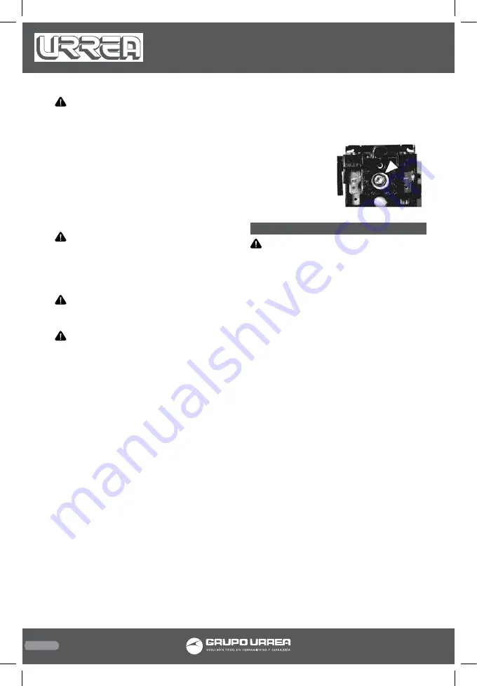
ADJUSTMENT CONTROLS
All pressure switches have a range adjustment
control (A). Some pressure switches also have a
differential adjustment (B) control. On switch-
es without a differential adjustment control,
the span between cut-in and cut-out pressure
levels switches is factory set for 40 ± 4 PSIG and
cannot be adjusted.
NOTE: Some pressure switches are equipped
with an on-off lever used to open and close the
electrical contacts inside the switch. THIS LE-
VER IS NOT A DIFFERENTIAL ADJUSTMENT
CONTROL. The pressure switches with the on/
off lever do not have a differential adjustment
control.
ADJUSTMENT PROCEDURES
(SWITCHES WITH-
OUT DIFFERENTIAL ADJUSTMENT CONTROL)
1. Remove the pressure switch cover.
2. Adjust the range by turning the range ad-
justment screw clockwise (in) to increase the
cut-out point or counter-clockwise (out) to de-
crease the cut-out point.
NOTE: One full turn changes the setting ap-
proximately 2 PSIG.
3. Replace cover, reconnect power supply and
start the compressor.
4. Note the pressure
gauge reading at
which the compressor
cuts out.
5. Repeat adjustment
procedure if neces-
sary.
MAINTENANCE
WARNING: It is recommended that all the
repair or replacement for the tool shall be per-
formed by a qualified service technician.
MAINTENANCE SCHEDULE
Daily or before each operation:
• Check for oil leaks.
• Check lubricant level. Fill as needed.
• Drain receiver tank condensate (if automatic
draining device is not provided). Open manual
drain valve and collect and dispose of conden-
sate accordingly.
• Test drain valve for proper operation.
Clean filter screen if needed.
• Check for unusual noise and vibration.
• Ensure beltguards and covers are securely in place.
• Ensure area around compressor is free from
rags, tools, debris, and flammable or explosive
materials.
• Check system oil pressure on pressure lubri-
cated models while compressor is hot.
Weekly:
• Observe operation of safety/relief valves
while the compressor is running. Replace
safety/ relief valves that do not operate freely.
• Inspect air filter element(s). Clean if necessary.
Monthly:
• Inspect for air leaks. Squirt soapy water
around joints during compressor operation
and watch for bubbles.
• Check tightness of screws and bolts. Tighten
as needed.
• Inspect drive belts. Adjust if necessary.
• Clean exterior.
• Clean drain valve filter screen.
3 months / 500 hrs of operation:
• Change petroleum lubricant while crankcase
is warm.
• Drain compressor oil and clean oil sight glass.
COMP9303 manual.indd 18
23/06/15 14:26


