background image

18

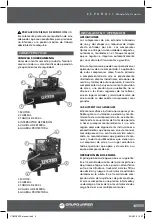
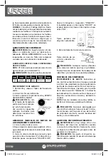
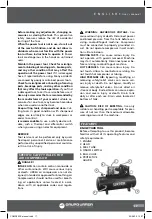
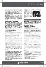
1. ENGINE.

2. HEAD.

3. 300 L TANK.

4. BALL VALVE.

5. PROTECTIVE GUARD.

INSTALLATION & OPERATION

APPLICATIONS

URREA’s standard one and two-stage lubri-
cated air compressors are single-acting, air-
cooled machines. Typical compressors are fur-
nished as compact, self-contained, air receiver 
tank mounted units  that are automatically 
regulated and driven by an electric motor. An 
air-cooled aftercooler, low oil level shutdown 
switch and automatic drain valve are among 
the optional accessories that can be furnished. 
Bare compressor pumps and baseplate-mount-
ed units are also available. These compressors 
may be used for a variety of compressed air ap-
plications. 
Application of these compressors as either 
a primary or supplementary  source of air is 
virtually unlimited in industrial plants, service 
stations and auto repair shops. Supplementary 
service includes such uses as furnishing air at 
pressure not carried in regular shop lines, air at 
isolated locations, and standby service for air 
when larger compressors are shut down.

GENERAL INFORMATION
This manual provides safe and reliable instruc-
tions for the installation, operation and main-
tenance of your air compressor. Carefully read 
this manual before attempting to operate or 
perform any maintenance. If you  are uncertain 
about any of the instructions or procedures 
provided in this manual, contact an authorized 
service center. We recommend you retain this 
manual, and all publications provided with 
your air compressor, in a location which is ac-
cessible to all personnel who operate and ser-
vice your compressed air equipment.

TWO-STAGE OPERATION

The basic principle of operation is as fol-
lows: On the suction stroke of the first-stage 
piston(s), air at atmospheric pressure enters 
the cylinders through the inlet filter(s) and 
then the inlet valves located in the head. 
On the compression stroke of the first-stage 
piston(s), the air is compressed to an interme-
diate pressure and discharged through the 
discharge valves(s) into common manifold(s). 
From the manifold(s) the air passes through 
the intercooler tubes, where the heat of first-
stage compression is removed. On the suction 
stroke of the second-stage piston this cooled 
air enters the second-stage cylinder through 
the inlet valve. 
The compression stroke of the second-stage 
piston compresses the air to the final discharge 
pressure and forces it out through the dis-
charge valve into the receiver tank or system. If 
cooling of the discharge air is required, an air-
cooled aftercooler should be installed between 
the compressor discharge and the receiver tank 
or system.
For maintaining the receiver tank or system air 
pressure within predetermined limits, the com-
pressor may be operated with automatic start 
& stop control or constant speed control regu-
lation. The type of regulation used depends 
upon the application.

RECEIPT & INSPECTION

Ensure adequate lifting equipment is available 
for unloading and moving the unit to the in-
stallation site.
NOTE: Lifting equipment must be properly 
rated for the weight of the unit.

 CAUTION: Lift the unit by the shipping skid 

only. Do not use the motor lifting eye to lift the 
entire unit. The motor lifting eye is for remov-
ing the motor from the unit only.

 CAUTION! Do not work on or walk under 

the unit while it is suspended.

INSTALLATION

SELECTING A LOCATION.
ELECTRIC MOTOR UNITS.
 For most electric 
motor units, select a relatively clean and dry 
well-lighted indoor area with plenty of space 
for proper ventilation, cooling air flow and ac-
cessibility. Provide 1,000 cubic feet of fresh air 

1

2

3

4

5

COMP95XX manual.indd   18

23/06/15   14:27

Summary of Contents for COMP9503

Page 1: ...515 Manual de Usuario y Garant a User s Manual and Warranty ATENCI N Lea entienda y siga las instrucciones de seguridad contenidas en este manual antes de operar esta herramienta WARNING Read understa...

Page 2: ...e Troubleshooting Air compressor Troubleshooting Electric draining Technical data Electric wiring diagram Warranty policy Normas generales de seguridad Seguridad el ctrica Seguridad personal Utilizaci...

Page 3: ...t cansado o bajo la influencia de drogas alcohol o medicamentos Un momento de distracci n mientras maneja herramientas el ctricas puede causar un da o personal serio Use equipo de seguridad Lleve siem...

Page 4: ...vista para el tipo particular de herramienta el ctrica te niendo en cuenta las condiciones de trabajo y el trabajo a desarrollar El uso de la herra mienta el ctrica para aplicaciones diferentes de las...

Page 5: ...la provisi n de aire a una presi n que usualmente no se ofrece en las l neas regulares de los talleres aire en lugares aislados y servicio de reserva de aire cuando se desconectan compresores m s gran...

Page 6: ...gadas 38 cm de las paredes y aseg rese de que la alimen taci n principal est claramente identificada y sea accesible A menos que los componentes el ctricos de la unidad est n especialmente protegidos...

Page 7: ...que receptor etc deben ser de segu ridad certificada para al menos la presi n de trabajo de la unidad Use tuber as y accesorios de cobre o hierro fundido de acero roscado o soldadura dura que tengan s...

Page 8: ...mpresor Si el disyuntor au tom tico posee una palanca ON AUTO OFF lleve el interruptor a la posici n ON AUTO Si launidad posee un interruptor ON OFF en el panel de control lleve el interruptor a la po...

Page 9: ...sario re pita el procedimiento de ajuste MANTENIMIENTO ADVERTENCIA Es recomendable que todas las reparaciones o reemplazos sean realizados por una persona de servicio t cnico calificado Siempre verifi...

Page 10: ...descritos m s abajo para ajustar y medir correctamente la tensi n 1 Mida la longitud del tramo t de la trans misi n 2 Determine la cantidad de flexi n en pulga das que se requiere para medir la fuerza...

Page 11: ...el lubri cante existente y vuelva a llenar con uno ade cuado V lvulas del compresor rotas carbonizadas sueltas o con filtraciones Inspeccione las v lvulas Limpie o reempl celas seg n sea ne cesario I...

Page 12: ...la v l vula piloto Ajuste la v lvula piloto El descargador del interruptor de presi n tiene filtraciones o no funciona Realinee el v stago o reemplace RUIDO EXCESIVO DURANTE LA OPERACI N Rueda de ban...

Page 13: ...arrancador Calefactores incorrectos de sobrecarga del arrancador Instale calefactores correctos de sobrecarga del arrancador Comun quese con un electricista Deficiente regulaci n de la potencia l nea...

Page 14: ...CEITE DEL RET N DEL EJE Ret n del cig e al gastado o cig e al cortado Reemplace el ret n Si es necesario instale un manguito de eje Instale el juego ahorrapasos de rodamientos biela de conexi n LA V L...

Page 15: ...Limpie el colador E S P A O L Manual de Usuario ESPECIFICACIONES T CNICAS COMP9505 COMP9503 COMP9510 COMP9515 VOLTAJE FRECUENCIA CAPACIDAD DEL TANQUE CAUDAL A 90 PSI CAUDAL A 150 PSI PRESI N M XIMA N...

Page 16: ...n while operating pow er tools may cause a serious personal injury Dress properly Do not wear loose clothing or jewellery Contain long hair Keep your hair clothing and gloves away of moving parts Loos...

Page 17: ...lt in a risk of injury SPECIFIC SAFETY RULES FOR AIR COMPRESSOR DANGER INTAKE AIR Can contain carbon monoxide or other contaminants Will cause serious injury or death URREA air compressors are not de...

Page 18: ...n s air at atmospheric pressure enters the cylinders through the inlet filter s and then the inlet valves located in the head On the compression stroke of the first stage piston s the air is compresse...

Page 19: ...NTING WARNING Remove the unit from the skid before mounting The compressor must be bolted to a firm level solid foundation such as a concrete floor using the vibration isola tion pads Installation on...

Page 20: ...men tary starting current of an electric motor is greater than its full load current Time delay or slow blow fuses are recommended COMPRESSOR LUBRICATION CAUTION Do not operate without lubri cant or w...

Page 21: ...t have a differential adjustment control ADJUSTMENT PROCEDURES SWITCHES WITH OUT DIFFERENTIAL ADJUSTMENT CONTROL 1 Remove the pressure switch cover 2 Adjust the range by turning the range ad justment...

Page 22: ...y available spreader or other belt tension ing device can also be helpful Follow the procedures outlined below to cor rectly set and measure tension 1 Measure the span length t of the drive 2 Determin...

Page 23: ...ve clogged leaking or de fective Inspect valve and clean repair or re place as required Piston rings damaged or worn broken rough or scratched Excessive end gap or side clear ance Install Ring Gasket...

Page 24: ...ping Check tubing and connections Tighten joints or replace as required Pressure switch differential too narrow Adjust pressure switch to increase differential if dif ferential adjustment provided Ins...

Page 25: ...ep Saver Kit Ambient temperature too low Install crank case heater kit Relocate compressor to warmer environment OIL IN DISCHARGE AIR OIL PUMPING Lubricant viscosity too low Drain existing lu bricant...

Page 26: ...electrical supply Apply power Timer malfunction Replace timer Clogged port Clean valve Solenoid valve malfunction Replace solenoid valve Clogged strainer Clean strainer TECHNICAL DATA COMP9503 COMP95...

Page 27: ...R ESTE COMPRESOR NO CUENTA CON ARRANCA DOR MAGN TICO NOTA Conecte la l nea de alimentaci n al arrancador No conecte la l nea de alimenta ci n al interruptor de presi n Conecte el cable de conexi n a t...

Page 28: ...fesionales S A de C V garantiza este producto por el termino de 1 a o en sus piezas componentes y mano de obra con tra cualquier defecto de fabricaci n a partir de la fecha de entrega Fecha de venta _...

Reviews: