20
CONDENSATE DISCHARGE PIPING. If installing
a condensate discharge line, the piping must
be at least one size larger than the connection,
as short and direct as possible, secured tightly
and routed to a suitable drain point or waste
container. Condensate must be disposed of in
accordance with local, state, and federal laws
and regulations.
WARNING: If an aftercooler, check valve,
block valve, or any other restriction is added
to the compressor discharge, install a prop-
erlysized ASME approved safety/relief valve
between the compressor discharge and the
restriction.
INSTALLING ELECTRICAL WIRING (ELECTRIC
MOTOR UNITS)
WARNING: Electrical installation and ser-
vice should be performed by a qualified elec-
trician who is familiar with all applicable local,
state and federal laws and regulations.
GENERAL. The motor rating, as shown on the
motor nameplate, and the power supply must
have compatible voltage, phase and hertz
characteristics.
MAGNETIC STARTER. If the motor installed on
your unit has a motor reset button, it does not
require a magnetic starter. If the motor does
not have this button and the unit does not
have a factory-installed starter, install a mag-
netic starter with thermal overload protection.
Follow the manufacturer’s instructions for in-
stallation. URREA cannot accept responsibility
for damages arising from failure to provide
adequate motor protection.
FUSES. Refer to the NEC to determine the
proper fuse or circuit breaker rating required.
When selecting fuses, remember the momen-
tary starting current of an electric motor is
greater than its full load current. Time-delay or
“slow-blow” fuses are recommended.
COMPRESSOR LUBRICATION
CAUTION: Do not operate without lubri-
cant or with inadequate lubricant. URREA is
not responsible for compressor failure caused
by inadequate lubrication.
SYNTHETIC COMPRESSOR LUBRICANT.
NOTE: For compressors with this feature, use
two stages oil with viscosity of 70; DO NOT use
automotive oil.
FILLING PROCEDURES:
1. Unscrew and remove the oil fill plug.
2. Fill the crankcase with lubricant.
3. Replace the oil fill plug HAND TIGHT ONLY.
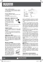
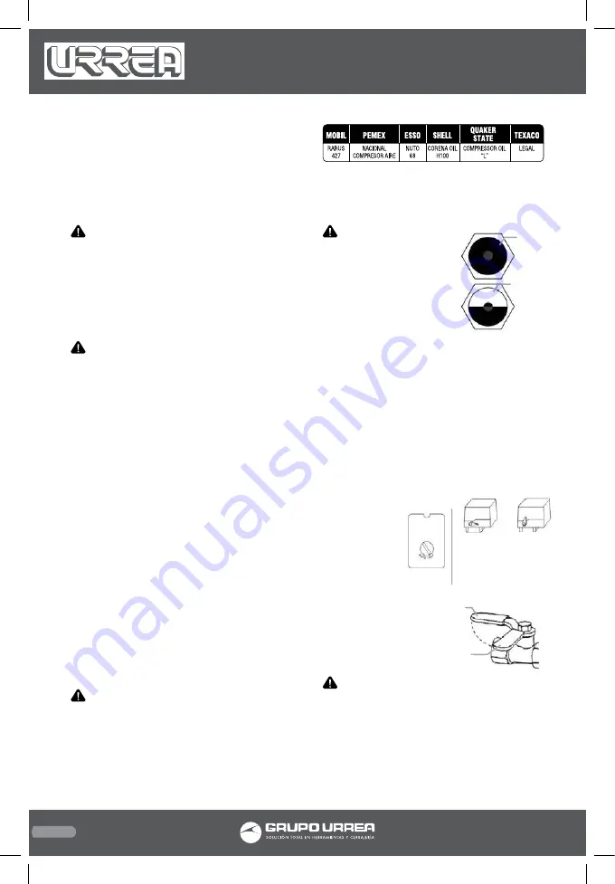
CAUTION: Do not re-
move the oil fill plug while
the compressor is running.
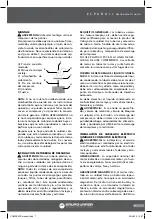
Refer to the following ta-
ble for crankcase capacity.
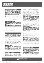
Use one of the following
methods illustrated to de-
termine when the crank-
case is full.
START-UP (ELECTRIC MOTOR DRIVEN MODELS)
1. Close the service valve.
2. Release any remaining tank pressure by
slowly opening the manual drain valve.
3. Close the manual drain valve and apply pow-
er to the compressor.
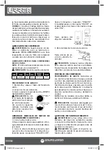
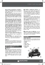
If the pressure switch is equipped with an “ON/
AUTO-OFF” lever, flip the switch to the “ON/
AUTO” position. If the unit is equipped with
a control panel “ON/OFF” switch, move the
switch to the “ON” position.
Typical Pressure
Switch
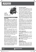
4. Slowly open the service valve.
Typical Service Valve
(A = Open, B = Closed)
CAUTION: Unusual noise or vibration indi-
cates a problem. Do not continue to operate
until you identify and correct the source of the
problem.
COMPRESSOR CONTROLS
ADJUSTMENT PROCEDURE. Select either auto-
matic start and stop control or constant speed
control by adjusting the knob on the auxiliary
ON/AUTO
OFF
ON/AUTO
OFF
A
B
Over-
filled
Optimal
quantity
COMP95XX manual.indd 20
23/06/15 14:27

