12
E N G L I S H
• Rubber Boot
• Auto Polarity
• Battery Replacement Indicator
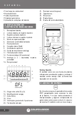
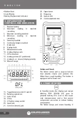
3. EXPLANATION OF
CONTROLS AND INDICATORS
1. Replace battery
2. Maximum reading in max/min
recording
3. Max/min recording enabled
4. Minimum reading in max/min
recording
5. Stand by enabled
6. Continuity beeper enabled
7. Diode test
8. Display hold
9. Measurement units
10. Analog display scale
11. Off scale arrow
12. Analog pointer (41 positiones)
13. Analog (+ or - shown) display polarity
14. Manual range
15. Toggle between volts DC and AC
16. Ranging operations
17. Volts DC/AC
18. Ohms
19. 6 Position rotary switch
20. Input jack
21. Common (return) jack
22. Capacitance
23. Frequency
24. Logic probe
25. Continuity/diode test
Holster and Stand.
The Meter comes with a snap-on holster
that absorbs shocks and protects the
Meter from rough handling. The holster is
equipped with a stand rest.
4. STAND BY MODE
In Standby mode, the display just except
blinking STBY (STAND BY) goes to
preserve battery life. And in this mode
only microprocessor and a few power
components are active to reduce battery
consumption.
The Meter beeps and enters Standby if
Summary of Contents for UD18
Page 18: ...18 NOTAS NOTES...
Page 19: ...19 NOTAS NOTES...


