E N G L I S H
55
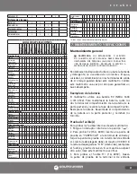
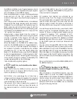
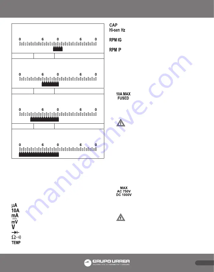
TRIGGER LEVEL INDICATED BY BAR GRAPH
-1
+1.68V
-0.50V
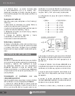
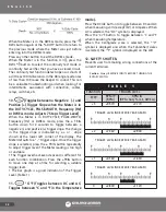
TRIGGER LEVEL INDICATED BY BAR GRAPH
-2
+1.26V
-1.95V
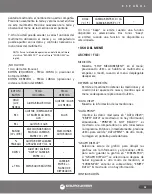
TRIGGER LEVEL INDICATED BY BAR GRAPH
-3
+0.69V
-4.38V
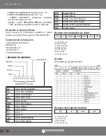
TRIGGER LEVEL INDICATED BY BAR GRAPH
13. OFF.
Power to the Meter is turned off.
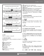
14. ROTARY SWITCH.
Describes functions that are selected by setting the
rotary switch.
Microamperes DC/AC.
Amperes DC/AC.
Milliamperes DC/AC.
Millivolts dc only.
Volts DC/AC.
Diode test.
Resistance / Continuity test.
Temperature.
Capacitance (Autoranging only).
Frequency (Non - automotive frequency)
measurement.
RPM measurement on 2 or 4 stroke engines
using the Inductive Pickup on a spark plug wire.
RPM measurement on 1 to 12 cylinder engines
using the test leads in the primary side of the ignition
coil and DUTY-CYCLE, Hz (automotive) & DWELL
measurement.
15. RS-232C INTERFACE.
Enables this Meter to serially communicate with a DOS
computer in all function ranges.
16.
The maximum current that you can measure at this
terminal is 10 Amps DC/AC. This terminal is fuse-
protected.
17.
Refer to the user’s manual before using this Meter.
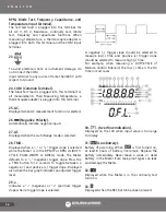
18. A (Amperes Input Terminal).
The red test lead is plugged into this terminal for
measuring current on the 4A or 10A AC or DC Ampere
functions.
19. mA μA (MilliAmp/MicroAmp Input Terminal).
The red test lead is plugged into this terminal for
measuring mA or _A on either AC or DC Ampere
functions.
20.
The maximum voltage that this Meter can measure is
1000V DC or 750V AC RMS.
21.
Be extremely careful when making high-voltage
measurements; DO NOT TOUCH TERMINALS OR TEST
LEAD PROBE ENDS.
22. VΩRPM CAP TEMP (Volts, Resistance,
Summary of Contents for UD88
Page 94: ...94 NOTAS NOTES ...
Page 95: ...95 NOTAS NOTES ...

