7
E N G L I S H •
User's Manual
used, the tool should be manually lubricated. To
manually lubricate the tool, disconnect the air-
line and put 2 to 3 drops of suitable pneumatic
motor lubricating oil into the hose end (inlet) of
the tool. Reconnect tool to the air supply and
run tool slowly for a few seconds to allow air to
circulate the oil. If the tool is used frequently,
lubricate it on a daily basis or lubricate it if the
tool starts to slow or lose power.
IMPORTANT:
design the air supply line to
ensure maximum operating pressure in the air
inlet of the tool. Condensation drain valve on
bottom outlets of the pipe, air filter and com-
pressor tank daily.
Install a safety coupling (sliding valve) and use
a hose and couplings restraint in any hose cou-
pling without internal damper to prevent the
hoses whiplash in the event that fails or is dis-
connected.
It is recommended that the air pressure at the
tool be 90 PSI while the tool is running so the
maximum RPM is not exceeded. The tool can be
run at lower pressures but should never be run
higher than 90 PSI. If run at lower pressure the
performance of the tool is reduced.
CONNECTION TO AN AIR SOURCE
1. Never connect to an air source that is capa-
ble of exceeding the pressure specified by the
supplier. Over pressurizing the tool may cause
bursting, abnormal operation, breakage of
the tool or serious injury to persons. Use only
clean, dry, regulated compressed air at the rated
pressure or within the rated pressure range as
marked on the tool. Always verify prior to using
the tool that the air source has been adjusted
to the rated air pressure or within the rated air-
pressure range.
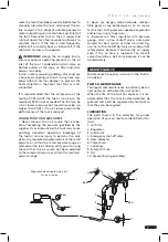
Diagrama de conexión de aire /
Air line assembly
24h
48h
90 psi
2. Never use oxygen, carbon dioxide, combus-
tible gases or any bottled gas as an air source
for the tool. Such gases are capable of explosion
and serious injury to persons.
3. Incorporate a filter, regulator with pressure
gauge, oiler, in-line shutoff valve, and quick
coupler for best service, as shown on next fig-
ure. An in-line shutoff ball valve is an important
safety device because it controls the air supply
even if the air hose is ruptured. The shutoff
valve should be a ball valve because it can be
closed quickly.
MAINTENANCE
Maintenance frequency is shown in the illustra-
tion below.
PARTS & MAINTENANCE
Tool repair and maintenance should only be car-
ried out by an authorized Service Center.
When the life of the tool has expired, it is rec-
ommended that the tool be disassembled, de
greased and parts be separated by material so
that they can be recycled.
LUBRICATION
The parts shown in the assembly for proper
operation of your air tools are identified as fol-
lows:
1. Air filter.
2. Regulator.
3. Lubricator.
4. Emergency shut-off valve.
5. Hose diameter.
6. Thread size.
7. Coupling.
8. Safety Air Fuse.
9. Oil.
10. Grease (During assembly).


