Document Title:
MTP
®
Loopback Casing Installation
Document Number: AEN-1430, Rev. 1.0
15 of 17 THE USE OF SAFETY GLASSES FOR EYE PROTECTION IS RECOMMENDED
Appendix A
Testing
A.1
Endface Geometry
Refer to AEN-1915, “US Conec Recommended MT Ferrule Endface Geometries”.
A.2
Insertion Loss (IL)
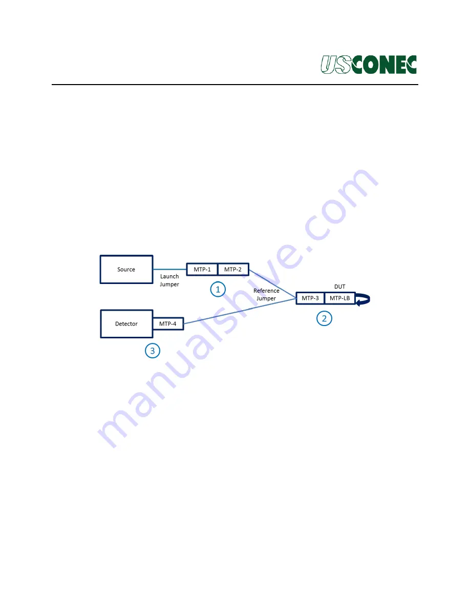
The IL measurement procedures in this section reference Figure A.2. This section applies
to both one-row and two-row loopback assemblies.
Note:
Make sure all ferrule end faces are inspected and clean. For testing a one-row
loopback, MTP-1, MTP-2, and MTP-4 can be replaced with individual single-
fiber connectors (e.g. LC, SC, etc.).
Figure A.2
A.2.1
It is recommended to use index matching gel between the mated pair MTP-1 and
MTP-2 at Position 1. The index matching gel will minimize potential polishing
anomalies at Position 1.
A.2.2
It is strongly recommended that MTP-3 uses the same grade ferrule as the Device
Under Test (DUT), which is the loopback assembly. Verify Encircled Flux
compliance at MTP-3 at the wavelength under test.
A.2.3
Insert MTP-3 into the Detector and reference. Mate MTP-3 and the DUT at
Position 2. Insert MTP-4 into the Detector at Position 3 to measure the IL of the
DUT at Position 2.
Note:
The measured IL of the DUT will be the result of two mated pairs because
of the loopback.


