24
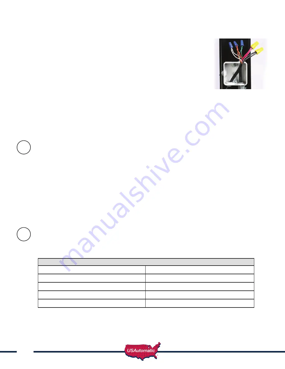
5. Route the linear actuator cable into the junction box through the bottom of
the box and determine length. Allow ample slack in the cable for actuator
movement when opening and closing the gate. Cut cable longer than needed
for future servicing.
6. Remove at least 2 inches of the exterior black jacket on both cables routed
into the junction box. Strip back approximately 1/2 inch of insulation from all
wires. Connect the wires from each cable, matching color to like color with
wire nuts. Pull firmly on all wires to be sure all connections are tight.
7. Install rain tight cover on junction box.
8. Remove at least 2 inches of the exterior black jacket on the pigtail cable
(saved from step 2) and on the remaining end of the extension cable
previously routed into the Ranger control box (step 4). Strip back approximately 1/2 inch of
insulation from all wires. Connect the wires from each cable, matching color to like color with wire
nuts. Pull firmly on all wires to be sure all connections are tight.
9. Do not plug into control board at this time.
IMPORTANT: The length of the extension cable should be as short as possible.
Installing Monitored Entrapment Protection Devices
Effective January 12, 2016 A vehicular gate operator or vehicular barrier (arm) operator shall have
provisions for, or be supplied with, at least two independent entrapment protection means as specified
in current UL325 standard Table 31.1. At installation, both entrapment protection devices must be
installed and operational before gate operation is allowed.
SYSTEM MANUFATURED AFTER JAN. 12, 2016 WILL NOT OPERATE WITHOUT 1 OF THE 2
FOLLOWING TYPES OF MONITORED ENTRAPMENT PROTECTION DEVICES CONNECTED
AND OPERATIONAL.
When the installation requires more than 1 monitored contact edge or monitored photo eye, the
Monitored Entrapment Device Expansion Modual must be installed. (USAutomatic Part# 500015)
Monitored Photo Eye (Type B1) Installation
for Entrapment Protection ONLY.
Connect wires per the table below: All wiring should be done with power disconnected from
control board.
Photo Eye wiring for Entrapment Device Protection
Photo Eye Connections
Ranger Control Board Connections
Power +12 vdc
J2 pin 5
Power ground / O
J2 pin 2 or pin 7
Common
J2 pin 2 or pin 7
N/C contact
J2 pin 8
The energy saving design of the control board will only apply 12 vdc to the photo eye when the gate is
in operation. During instal12 vdc power is required to align the photo eye beam.
12
12
a


