background image

USAUTOMATIC

ELECTRIC GATE LOCK

Part Number 070510

Installation Manual

The USAutomatic Electric Gate Lock works with an automatic gate operator to securely lock the gate into 

position without having to get out of your vehicle. The USAutomatic Electric Gate Lock is wired into the gate 

operator control box, so that when an input device such as a transmitter or keypad is used to open the gate, 

the USAutomatic Electric Gate Lock disengages and the gate will open. When the gate closes, the gate lock 

automatically engages to secure the gate in the closed position.

The USAutomatic Electric Gate Lock provides an extra level of protection.

In addition to protection, it provides stability for the gate by securely locking the gate into position, so that  

damaging effects, such as wind, are minimized. The result is the gate and automatic gate operator will stay 

in excellent working condition for a much longer time.

The USAutomatic Electric Gate Lock Assembly works with most types of gates and mounting applications.

NOTE:

 In order for the USAutomatic Electric Gate Lock to work properly, the gate must close firmly against 

the stop gate post or closed position stop plate. To achieve the desired closed position, you may need to 

slightly adjust the gate operator closed limit set points. Instructions for adjusting the closed limit set points 

are included in your automatic gate operator manual.

THIS LOCK IS DESIGNED FOR 12VDC CONTROL SYSTEMS.  

PLEASE NOTE OPERATING VOLTAGE IS 10VDC TO 14VDC

PLEASE READ THE ENTIRE MANUAL CAREFULLY PRIOR TO INSTALLATION.

Electric Gate Lock Part Number 070510 Technical Information

Operating Voltage

10 vdc to + 14 vdc

Nominal Activation Current

< 250 milli amps

Duty Cycle

Intermittent

Construction

Steel Powder Coated Black Housing

Locking Mechanism

Spring Loaded self-latching

Min Recommended Supply Voltage Wire Guage

18 gauge / .8 mm2

Emergency Release Type

Removable Strike Pin

Installation Type

Bolt or Weld On Brackets

Periodic Service Recommendation

Lightly Grease Strike Pin

Temperature Range

-30 C to +85 C

Shipping Weight

10 lbs / 4.53 kgrams

IMPORTANT: 

Summary of Contents for 070510

Page 1: ...Lock Assembly works with most types of gates and mounting applications NOTE In order for the USAutomatic Electric Gate Lock to work properly the gate must close firmly against the stop gate post or closed position stop plate To achieve the desired closed position you may need to slightly adjust the gate operator closed limit set points Instructions for adjusting the closed limit set points are inc...

Page 2: ...and hinge post The Lock Housing should NEVER be welded Internal parts can be damaged by excessive heat Bolt on brackets are provided and are acceptable but may require frequent service to keep tight They must be very securely attached i e carriage bolts with lock nuts and washers 1 2 3 4 5 6 7 8 9 10 11 1 2 3 4 6 7 8 9 10 5 Lock Housing Part 070660 Lock Mounting Bracket Part 070670 Strike Bracket ...

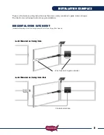
Page 3: ... The Electric Lock will adapt to almost any gate installation HORIZONTAL SWING GATE MOUNT Horizontal Mounting of Lock on Swing Gate with Pull to Open Swing Gate Opener Lock Mounted on Swing Gate Wire from lock to gate controller Conduit under drive Lock Mounted on Swing Gate Post INSTALLATION EXAMPLES ...

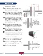
Page 4: ...and true as possible Mount the strike bracket without the strike pin to the receptor post using the two 6 carriage bolts and lock nuts supplied to allow for adjustment do not tighten completely Fig B Now install the lock mounting bracket on the center of the gate rail using the 4 carriage bolts and lock nuts supplied again do not tighten completely Fig B Before mounting the electric lock to the br...

Page 5: ... of any Moving parts during powered operation or testing Re connect operator arm Reconnect power to operator motor plugs Initiate operator to open and visually observe lock to see if Lock Pin retracts during opening and extends during closing It is important that power is only applied during the opening cycle All power to the electric lock should be off during the closing cycle or in the rest posi...

Page 6: ...6 This page intentionally left blank ...

Page 7: ...er of a new product that was not sold as is or as surplus Limited Warranty Service For assistance in the continental U S A in obtaining the benefit of the Limited Warranty please carefully follow these steps 1 Contact USAutomatic customer service 1 888 204 0174 Please have the model number of the Product available to give to the customer service representative The customer service representative w...

Page 8: ... USAutomatic LTD 2014 rev A All rights reserved No part of this may be reproduced by any means without the expressed written consent of the publisher ...

Reviews: