36
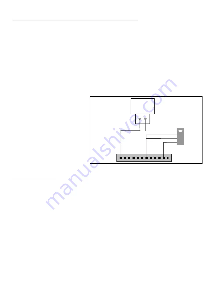
Security Shunt – Used to control a Photo-Eye
If installing a photo-eye on a solar gate operator the standby current draw of the photo-eye will drain the
battery. The Patriot control board is designed to control the photo-eye to avoid this common problem.
The Patriot control board will only apply dc power to the photo-eye when the gate is opened.
If wired as follows.
NOTE: Do not hold the gate open when using this feature to control the photo-eye +12 vdc power.
Remember that the photo-eye will be powered up when the gate is not closed. Gate open power is
on. Contact the factory for more information.
The photo-eye should have 4 wires that need to be identified:
1
+12 vdc power
2 Ground
3
N/O or Normally Open
4
Common or common ground
After wiring as shown below locate the DS2 dipswitches on the Patriot control board (see page 21) and turn on
the security shunt circuit enable dipswitch.
Accessory Wiring
The +12 vdc output is protected with a 1.5 amp auto-resetting fuse.
Solenoid Lock
– This is a +12 vdc output that can 12 volts two different ways.
1.
If DS2 switch 1 is turned “on” and DS1 switch 5 is “OFF,” the +12 vdc will come on a half second
before the gate begins to open after activation. Once the gate begins to move, the output will go to 0
volts in 4 seconds.
2.
The other option is to turn DS2 switch 1 and DS1 switch 5 on. With this setting the solenoid lock output
will be +12 vdc a half second before the gate begins to move and remain at +12 vdc until 3 seconds after
the gate has stopped on a limit. For example, this can be used to turn on a gate in motion siren or light.
Magnetic Lock
– This is a +12 vdc output.
Whenever the gate reaches the closed limit the +12 vdc will be present and remain until the gate is
activated to open. The +12 vdc output will be turned “off” one half second before the gate begins to
open.
PHOTO-EYE
POWER + 12
Security Shunt
terminals on
Patriot control
board
POWER + 12
POWER ground
COMMON
N/O
Control Board
J2


