background image


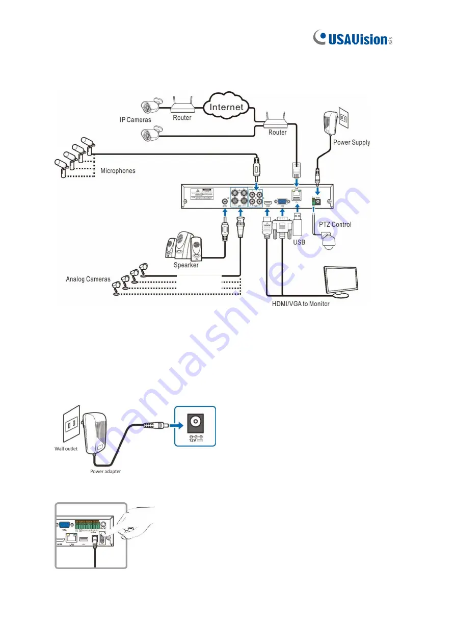
2.2    Connection Diagram 


2.3    Power Supply Connection 

Caution

: Use only the supplied power adapter of the DVR. 


Connect one end of the power adapter to the power connector on the back of the DVR. Plug the 

other end of the power adapter into the wall outlet.   


For specific models, press the 

Power Switch

 to turn on the power. 

Speaker 

Summary of Contents for UA-XVL1610

Page 1: ...Before attempting to connect or operate this product please read these instructions carefully and save this manual for future use UVSUAV102 QG A Quick Start Guide UA XVL810 UA XVL1610 UA XVR810 ...

Page 2: ...ntal or consequential damages arising from the use of the information or products contained herein Features and specifications are subject to change without notice GeoVision Inc 9F No 246 Sec 1 Neihu Rd Neihu District Taipei Taiwan Tel 886 2 8797 8377 Fax 886 2 8797 8335 http www geovision com tw Trademarks used in this manual GeoVision the GeoVision logo and GV series products are trademarks of G...

Page 3: ...n 8 2 1 HDD Installation 8 2 2 Connection Diagram 9 2 3 Power Supply Connection 9 3 Getting Started 10 3 1 Start Wizard 10 3 1 1 Start Wizard 10 3 1 2 Connecting IP Cameras 10 3 2 Live View Overview 12 3 2 1 Main Window 12 3 2 2 Task Menu Bar 14 3 2 3 Camera Quick Toolbar 14 4 Remote Access via Web Client 16 4 1 Basic System Requirements 16 4 2 Looking Up the Dynamic IP Address 17 4 3 Web Client M...

Page 4: ...e following sections you will learn about the basic installations and configurations For more details see UA XVL1610 UA XVR810 User s Manual 1 1 Packing List UA XVL810 UA XVL1610 UA XVR810 USB mouse 3 5 HDD screw Kit Power adapter DC 12V 2A 24W 2 5 HDD screw kit Download guide ...

Page 5: ...10 Font Panel Item Description Power LED Show constant green when power is supplied HDD LED Blink red when the HDD is writing or reading data No LED when no HDD is installed USB port Connect the supplied mouse or USB flash memory ...

Page 6: ...put devices BNC port HDMI Connect to your digital TV or monitor with HDMI input VGA Connect to your TV or a monitor with VGA input LAN Connect to your home network USB port Connect the supplied mouse or USB flash memory Reset Load default settings of the DVR Note The Reset button is below the USB port Poke the Reset button to load default settings RS 485 Connect to PTZ devices Power Connect to the...

Page 7: ... View Item Description Power LED Show constant green when power is supplied HDD LED Blink red when the HDD is writing or reading data Show no LED when no HDD is installed USB port Connect the supplied mouse or USB flash memory ...

Page 8: ...MI Connect to your digital TV or monitor with HDMI input LAN Connect to your home network USB port Connect the supplied mouse or USB flash memory Reset Load default settings of the DVR Note The Reset button is below the USB port Poke the Reset button to load default settings Power Connect to the supplied power adaptor RS 485 Connect to PTZ devices Sensor Alarm Optional Connect to external sensor a...

Page 9: ...nt View Item Description Power LED Show constant green when power is supplied HDD LED Blink red when the HDD is writing or reading data No LED when no HDD is installed USB port Connect the supplied mouse or USB flash memory ...

Page 10: ... of the DVR Note The Reset button is next to the HDMI port Poke the Reset button to load default settings VGA Connect to your TV or a monitor with VGA input HDMI Connect to your digital TV or monitor with HDMI input LAN Connect to your home network USB port Connect the supplied mouse or USB flash memory Power Connect to the supplied power adaptor RS 485 Connect to PTZ devices Sensor Alarm Optional...

Page 11: ...orts 3 5 and 2 5 SATA HDD of up to 8 TB only 2 The following procedures are for reference only The practical operation may be different depending on the model you purchased HDD Installation 1 Cut power firstly Unscrew both sides and rear panel to open the upper cover 2 Connect the data and power cables to the HDD and place the HDD on the DVR case Carefully flip the DVR case and secure the HDD to t...

Page 12: ...Use only the supplied power adapter of the DVR Connect one end of the power adapter to the power connector on the back of the DVR Plug the other end of the power adapter into the wall outlet For specific models press the Power Switch to turn on the power Speaker ...

Page 13: ...etting Started 3 1 Start Wizard 3 1 1 Start Wizard Click Start Wizard to proceed to the next step 3 1 2 Connecting IP Cameras After finishing setting Network Configuration and Date and Time this page appears ...

Page 14: ...ocol of the IP camera from the dropdown menu Select Onvif for UA B20004F UA B40004F UA B4000VF S UA D20002F UA D40002F UA D4000VF S UA R40002F SA GV IP cameras Select Private for UA B580F3 UA R500F2 UA R560F2 UA R580F2 UA R800F2 User Name User Name of the IP camera Password Password of the IP camera Note 1 The system fills in the ID and password using admin admin by default Make sure to enter the ...

Page 15: ... connected is a CVI camera IP This indicates that the camera connected is an IP camera 2 Status Icon This indicates that the DVR is currently recording This icon appears when the camera has detected motion The icon indicates that the external I O alarm device is triggered This icon indicates that the HDD is in error to work This icon indicates the HDD is unformatted This icon indicates the HDD is ...

Page 16: ...tes at the bottom of the live view screen Refer to 3 2 2 Task Menu Bar in the Quick Start Guide for details 6 System Date and Time Displays the system s date and time 7 OSD VIDEO LOSS The analog camera is disconnected No Camera IP camera is disconnected Decoding Failed The DVR doesn t support the current IP camera compression standard Change the compression standard to H 264 Click to open Quick Ad...

Page 17: ...to switch among real time balanced or smooth view This function only effects the live view video quality by bitrate and frame rate without impacting the recording quality Manual To start or stop Manual Record and Manual Alarm System To view system information channel information record info and network state This icon appears if the network is disconnected 3 2 3 Camera Quick Toolbar Click to manua...

Page 18: ...d the channel If the manual recording is in process the icon will be in red color Click one more time to stop manual record Click to save a snapshot of the current camera image Manual Capture must be enabled to use this feature Click to play the last 5 minutes of recording of this channel Click to enter PTZ control panel Click to zoom in the channel When the icon appears press and hold the left bu...

Page 19: ... Requirements Item Minimum Recommended CPU Intel Core i5 CPU Intel Core i5 CPU or higher RAM 4G or more 8G or more Hard Drive 500G or more 1000G or more Display RAM 2G or more 4G or more Display Resolution 1280 1024 1920 1080 OS Windows 7 or above Mac OS X 10 9 or above DirectX DirectX 11 Direct3D Acceleration Function Ethernet Adapter 10 100 1000M Ethernet Adapter IE 10 11 Mozilla Firefox V52 or ...

Page 20: ...with a dynamic IP address Follow the steps below to look up its IP address 1 Download and install the UVS Device Utility program here 2 On the UVS Device Utility window click Search to search for the devices connected in the same LAN 3 Find the device with its Mac Address and click on its IP address 4 The login web page appears ...

Page 21: ...n the Live video stream on off The button is in blue color if the live video streaming is on Record Click to start manually recording live streaming video Click again to stop recording Manual recordings are saved to your computer While in recording the button is in blue color Capture Click to save a snapshot of the current live display to your computer Bitrate Set camera to use mainstream sub stre...

Page 22: ...or recordings and snapshots taken using Web Client and choose file type for video files 4 Information Hover over to see system details 5 Exit Click to close the Web Client Manager 6 Color Click to display or hide the color controls 7 PTZ Setting Click to display or hide the PTZ controls for using PTZ cameras Refer to 7 3 1 Live Interface in UA XVL1610 UA XVR810 User s Manual for details 8 Live Vie...

Page 23: ... program here 2 On the UVS Device Utility window click Upgrade and check the box of the device you wish to upgrade the firmware on Optionally check the corresponding boxes to upgrade the firmware on several devices at a time 3 Click Open to locate the firmware file saved at your local computer 4 Type the username and password of the device 5 Click Upgrade to process the upgrade ...

Reviews: