

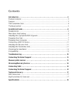


Summary of Contents for CrystalLink USB 3.0
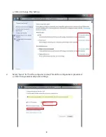
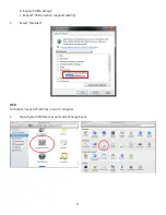
Page 20: ......
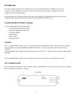
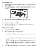
The USB Vision CrystalLink USB 3.0 is a cutting-edge connectivity solution. Discover how to unleash its full potential with the detailed Installation and User Manual. Easily download the comprehensive manual for free from our website, providing step-by-step instructions and enabling you to maximize your product experience.
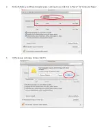
Page 20: ......


