background image


ZenCut Black User Manual 


Installation                                                                             

2-7 

2.4    Blade Installation 

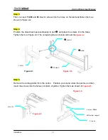
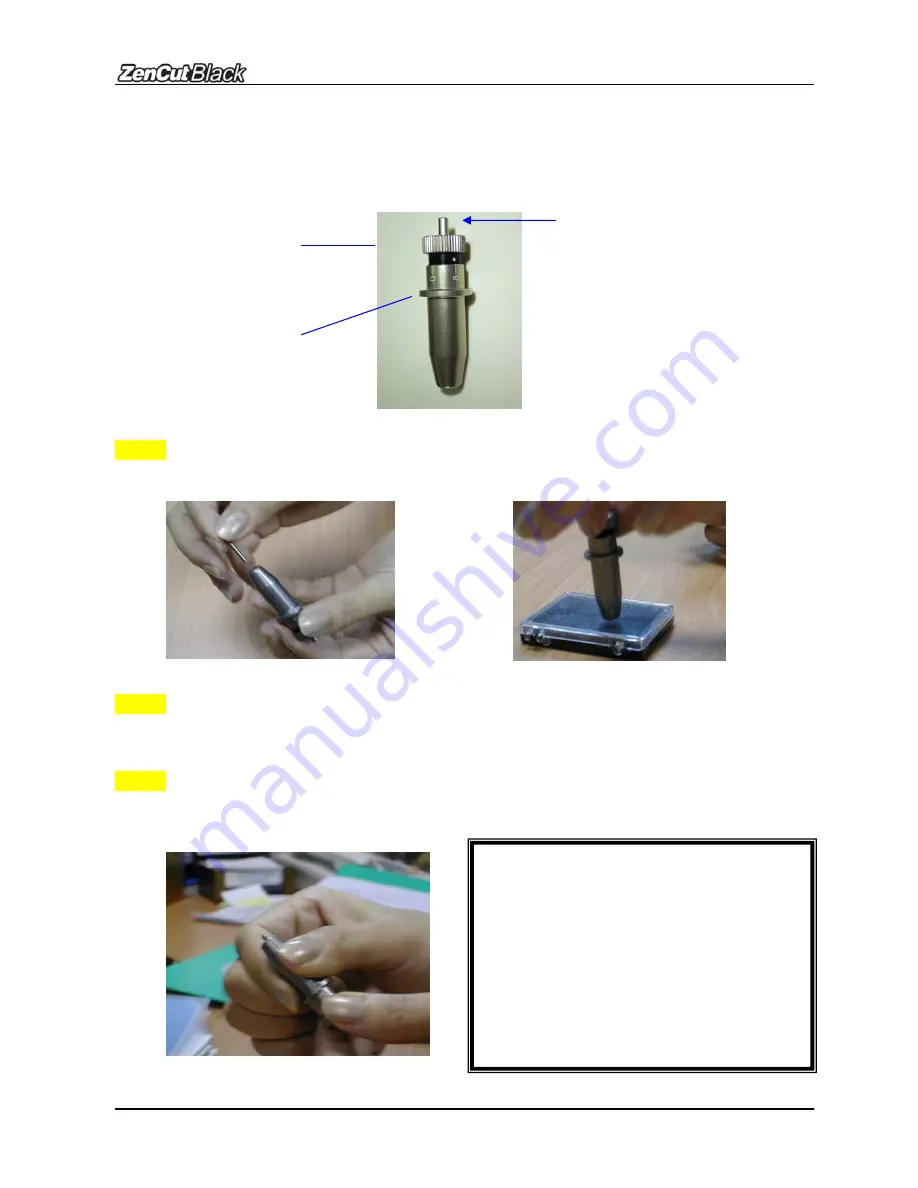
Figure 2-12 is the illustrator of the blade holder. Insert a blade into the bottom of the blade 

holder. Remove the blade by pushing the pin. Make sure that your fingers are away from the 

blade tip.   


 Pin 

Adjustment depth knob 

Outward ring

Figure 2-12 


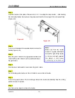
Step 1


Install blade (Figure 2-13).   


Step 2


Push the blade to the bottom of the blade holder. (Figure 2-14).   


Step 3


Adjust the blade tip to suitable length by rotating “blade tip adjustment screw” clockwise or   

counter-clockwise. (Figure 2-15).   

Figure 2-15 

Figure 2-14 

Tips: 

“The suitable length” means the blade’s 

length is adjusted 0.1mm more than 

film’s thickness. That is, if the thickness 

of film is 0.5mm, then blade’s length is 

properly adjusted 0.6mm and it can 

completely cut through the film layer 

without cutting through backing paper. 

Figure 2-13 


Summary of Contents for ZENCUT Black

Page 1: ...V1 June 09 User Manual...

Page 2: ...eded a deposit MUST be paid for the replacement at the time the part order is placed It will be refunded upon our receipt of the defective part You are responsible for shipping costs to and from our f...

Page 3: ...iage drums Also be careful of loose clothing and other foreign objects z Always connect the power cable to a grounded outlet z Always use the accessory power cable that is provided Do not bend or pinc...

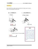
Page 4: ...ion is shown below O CORRECT INCORRECT Press DISABLE Press down Stop bar ENABLE Pull up bottom to release grip NOTE If the grips have clipped together due to incorrect operation you can use tweezers t...

Page 5: ...able Connections 2 5 1 USB Interface 2 10 2 5 2 Parallel Interface 2 10 2 5 3 RS 232 Interface 2 11 2 5 4 Data Transmitting 2 11 3 The Control Panel 3 1 The LCD Panel 3 1 3 2 Menu in On line Mode 3 2...

Page 6: ...6 3 Cleaning the Pinch Rollers 6 2 7 Trouble Shooting 7 1 Non Operational Problems 7 1 7 2 Operational Problems 7 2 7 3 Communication Problems 7 3 7 4 Software Problems 7 4 7 5 Cutting Quality Problem...

Page 7: ...50 1270mm ZCB 132S for media width 2 50mm 62 7 594mm ZCB 183S for media width 12 300mm 74 8 1900mm 1 2 Package Items The ZenCut Black package contains the following items Please check carefully before...

Page 8: ...exagon screw driver V 1 4 Accessory Bag z 1 User CD z 1 AC power Cord z 1 data cable RS 232C z 1 data cable Print cable z 1 data cable USB cable z 1 Blade Holder Assembly Installed in tool carriage of...

Page 9: ...ol Carriage performs cutting with the installed blade and pen with AAS module Alignment Rulers aligned media with clear guide line marks Grid Drums move the media back and forth during operation Slice...

Page 10: ...shes keep roll media in place while media is pulled from the roll Stand Beam stabilizes the stand Roll Holder Support supports roll holders Figure 1 3 H shape Stand supports the cutting machine Stand...

Page 11: ...nector RS232C used to connect the cutting plotter to a computer through a serial interface cable USB Connector used to connect the cutting plotter to a computer through a USB cable Parallel Interface...

Page 12: ...be enough space for the machine accessories and supplies z The working area should be stable and level to prevent machine vibration z Keep the temperature between 50 95o F 10 35o C in the work area z...

Page 13: ...in the accessory box of stand carton z 1 M6 L shape hexagon screw driver z 1 M5 L shape hexagon screw driver z 24 M6 screws z 4 hold plugs z 4 Stand Wheels z 1 Installation Guide for Stand Set Step 2...

Page 14: ...the screws into the holes Tighten them as Figure 2 3 The complete picture of stand will look like Figure 2 4 Step 5 Remove the cutting plotter from the carton Position your stand under the plotter and...

Page 15: ...tighten them up as shown in Figure 2 6 You can change decide roll holder support s position by inserting into different holes Step 7 Place two roll holders into the holes in the roll holder support Fi...

Page 16: ...M5 L shape hexagon screw driver z 1 M6 L shape hexagon screw driver for adjusting the screws of Roll Holders z 1 Installation Guide for Roll Holder Step 2 Put the 4 Plastic Feet under the Roll Holder...

Page 17: ...the M6 screws into the holes of Roll Holder support assembly and tighten them with M6 L shape screwdriver Like Figure 2 9 Step 5 Place the two roll holders into the holes of Roll Holder Support Figure...

Page 18: ...l blade Figure 2 13 Step 2 Push the blade to the bottom of the blade holder Figure 2 14 Step 3 Adjust the blade tip to suitable length by rotating blade tip adjustment screw clockwise or counter clock...

Page 19: ...increasing the cutting force the blade may still cut However once the blade is no longer provides a reliable cutting you should replace it with a new one The blade is a consumable item and must be rep...

Page 20: ...driver The USB driver was installed successful when a popup window shows USB Driver installed Connection Plug the USB cable into the ZenCut Black USB interface connector Plug the other end of the cabl...

Page 21: ...e to emulate HP GL or HP GL 2 commands therefore use DOS commands like TYPE or PRINT to output your file As long as the file is HP GL or HP GL 2 format the cutting plotter can output the data precisel...

Page 22: ...To display functions and error messages Power LED To indicate the power status light up power on light off power off 4 Arrow Keys To move position select function or change setting ENTER To set item o...

Page 23: ...bort Pause Setup Resume S F O L W T1M Sending data PAUSE FORCE Force 80 gf OK ENTER use to select ENTER to enable the setting Speed 72 cm s Select OK ENTER UP Speed 72 cm s Select OK ENTER Quality nor...

Page 24: ...anded Mode Width Expanded Mode Both Unexpanded Mode OverCut 0 00 1 00mm with an increment of 0 05mm Pouncing 0 200mm with an increment of 1mm English Chinese Metric cm gf or English measurement inch o...

Page 25: ...parameters of XY axes displayed press MISC key will enable fine tune movement press MISC key again to disable the function PAUSE RESUME To temporarily halt the cutting process To resume the process by...

Page 26: ...uts Note While the Offset value setting at 0 000 mm Set Tangential Mode will automatically be disabled Enable Pouncing To make perforated patterns In order to use this function Pouncing tool must be i...

Page 27: ...n 8 1 p 9600pbs 8 Bits with NO Parity 9600 o 8 1 p 9600pbs 8 Bits with ODD Parity 9600 e 8 1 p 9600pbs 8 Bits with EVEN Parity 19200 n 7 1 p 19200pbs 7 Bits with NO Parity 19200 o 7 1 p 19200pbs 7 Bit...

Page 28: ...ised Figure 4 1 Step 2 Load your media on the platen and slide it under the pinch rollers from either the front side or the backside The alignment rulers on the platen extension will help you to adjus...

Page 29: ...marks Figure 4 3 Step 4 Push the lever backward to lower down the pinch rollers Step 5 Turn on the power The tool carriage will measure the size of the media automatically Note 1 Always adjust the pos...

Page 30: ...roll media directly between the two roll holders Figure 4 6 Option B Use the media flanges Insert a roll media flange at the end of each roll media and tighten the thumbscrew until the roll media is f...

Page 31: ...t will cause t r a c k i n g p r o b l e m s Note Turn the roll downward to equalize tension across the media Figure 4 10 Step 5 Move the pinch rollers to the appropriate location and note that the pi...

Page 32: ...eters leave the margin 01 in 1 in 0 5mm 25mm in the left and right edges of the media Figure 4 11 01 in 1 in 01 in 1 in Pinch roller Figure 4 11 Pinch roller If the media length is greater than 13 fee...

Page 33: ...on When the cutting test is completed a test cut sample design appears Peel off the design to see if it can be easily separated from the media base If yes the setup tool force is appropriate If not or...

Page 34: ...ith a roll of heavy and wide vinyl or paper you need to use the AUTO UNROLL MEDIA function The following parameter settings are to help users get the best cutting quality The actual output quality may...

Page 35: ...the roll holder to secure the roll media 6 The protrusion length of the blade should be longer than the thickness of the vinyl Please check the Blade Specification About the Tool in Appendix Once all...

Page 36: ...ure a standard Accu Aligning System AAS II to guarantee precise contour cutting quality by detecting the registration marks printed around the graphic Notice Eliminate light sources from the side of t...

Page 37: ...come undetectable in AAS sensing process 5 2 2 AAS Calibration The first registration mark has a different design in order for AAS auto detection to identify the origin The following must be known for...

Page 38: ...rn that AAS II will auto detect four registration marks and contour cut images inside those marks Command Esc D1 XDist YDist Layout 4 L shaped marks at the 4 corners around the design 2 Segmental Posi...

Page 39: ...setting is recommended for testing Print out the testing graphic Please use printer capable of printing high resolution graphics Load the graphic to ZenCut Black and send the file to test the cutting...

Page 40: ...es set in cutter are X 0 50 mm Y 0 50 mm and the measurement is X1 0 25 mm Y 1 0 25 mm In following figure the Blue Line refers to the Y Value and the Red Line refers to the X value We need to adjust...

Page 41: ...hic that you want to print and cut in your software Create a contour for cutting around the graphic TIP 1 Leave some space between the graphic and contour line TIP 2 Create the contour in a separate l...

Page 42: ...k covers the grey area Suggested 30mm 1 18in margin on both left and right sides of media sheet Suggested 20 30mm 75 1 18in margin on top of media sheet and at least 50mm margin on the bottom edge to...

Page 43: ...5 Tips for AAS To get the best results in contour cutting please follow these tips Keep light sources simple and avoid illuminating from the sides of cutter Before operating AAS set the appropriate m...

Page 44: ...g Unplug the cutting plotter before cleaning Never use solvents abrasive cleaners or strong detergents for cleaning They may damage the surface of the cutting plotter and the moving parts Recommended...

Page 45: ...3 Cleaning the Pinch Rollers 1 If the pinch rollers require a thorough cleaning use a lint free cloth or cotton swab to wipe away the accumulated dust from the rubber portion of the pinch rollers To...

Page 46: ...s in your cutting plotter not the result of an interface problem a malfunction with your computer or a software problem Why is the cutting plotter not functioning Possible Causes 7 1 Non Operational P...

Page 47: ...n to reboot system Error Check Media Or Drum or X Motor This message indicates that there might be an obstruction to carriage relating to a problem on the Y axis Correct the problem and re power on to...

Page 48: ...tting plotter Yes No Try the connection between your cutting plotter and computer If it still does not work have your cutting plotter serviced Refer to the MISC key in Chapter 3 Description of Operati...

Page 49: ...the software vendor provide a sample file Most well known cutting software has drivers that are compatible with our cutting plotters If yours is not use software that has HP GL and HP GL 2 emulation s...

Page 50: ...2 4 Blade Installation Is the blade dull or chipped Yes No Replace with a new blade Is tool force set up properly The default for tool force is 80 gf Yes No Is the tool offset set up properly Adjust t...

Page 51: ...the USB cable is connected to computer When the USB driver is installed on one USB port and then the USB cable is re connected to another USB port on the same PC next time most computers will show th...

Page 52: ...ZenCut Black User Manual Trouble Shooting 7 7 1 Select Start Control Panel Add Hardware 2 Click Next 3 It will take a few moments to detect the USB port...

Page 53: ...ZenCut Black User Manual Trouble Shooting 7 8 4 Connect ZenCut cutter and select Yes I have already connected the hardware 5 Select USB PRINTER and click Next...

Page 54: ...ZenCut Black User Manual Trouble Shooting 7 9 6 Finish 7 Choose Install the software automatically Recommended...

Page 55: ...ZenCut Black User Manual Trouble Shooting 7 10 8 Wait a few minutes 9 Now you can use your ZenCut Black cutter ZenCut Black USB...

Page 56: ...hanical Resolution 0 00625mm Software Resolution 0 025 mm Repeatability 0 1mm Curve Arc Smoothing Yes Configurable Origin Yes Test Cut capability Yes Tangential Yes Repeat Yes Copy Yes Pouncing Yes Co...

Page 57: ...t For cutting reflective vinyl cardboard sandblast flock and stencil sharp edge 26500058G The blade is 60 with Green Cap 0 50 mm blade offset For cutting thin sandblast mask and stencil with friction...

Page 58: ...ting to the reference point OFFSET is the distance that the blade tip is displaced from the centerline of the blade Protrusion Length of the Blade Length of protrusion t1 t 2 2 but for your convenienc...

Page 59: ...le for CorelDRAW Version 11 12 13 14 Installation 1 Check the AAS CorelDraw Installer folder in ZenCut Black User CD and double click the AASIIInstaller exe file to run the installation program 2 Pres...

Page 60: ...ZenCut Black User Manual User Instructions 1 Open CorelDRAW finish editing all the files you wish to plot and select all the image at once 2 Select Tools Visual Basic Play CorelDRAW Plug In A 3...

Page 61: ...ance between marks and images Range 1mm 50mm Optimized Setting 5mm Segmental Positioning z X Step The distance of intermediate position on the X axis z Y Step The distance of intermediate position on...

Page 62: ...he necessary 4 marks on the picture 4 Now you can output the image file directly to ZenCut Black to run the AAS function You can also pull out a Hot Icon for the AAS II Plug in Step 1 Select Tools Cus...

Page 63: ...e ZenModule Zen_AASII and drag it to commands bar Step 3 If you want to have a different icon select Tools Customization Commands Appearance to import the graphics Choose an icon and press OK to finis...

Reviews: