background image

System description Fl Set 

01/21

Fl Set

14 

5.3 

Fl rear view  


Fig. 5.3: 

Fl rear view 


14  I/O connection 

15  Solenoid coil 

16  Serial number 

17  Pressure sensor connection 

18  Power supply connection 


Summary of Contents for FlowTimer+

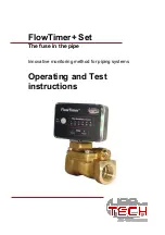
Page 1: ...FlowTimer Set The fuse in the pipe Innovative monitoring method for piping systems Operating and Test instructions ...

Page 2: ...21 Print date 22 02 2021 Copyright usetech GmbH This documentation including all its parts is protected by copyright Any use or modification outside the narrow limits of copyright law without the consent of the company usetech GmbH is prohibited and punishable by law This applies in particular to duplications translations microfilming and storage in electronic systems as well as processing in thes...

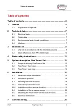
Page 3: ...m PPC 3000 Basic 10 4 Basic safety instructions 11 5 System description FlowTimer Set 12 5 1 Scope of delivery FlowTimer Set 12 5 2 FlowTimer front view 13 5 3 FlowTimer rear view 14 6 Installation 15 6 1 Measures before installation 15 6 2 Installation position 16 6 3 Installing the shut off valve 18 6 3 1 Installation position KFR valve 18 6 3 2 Installation position pressure boosting 19 6 4 Ins...

Page 4: ... duration 32 9 1 6 Changing the sensitivity 33 9 2 Status display illuminated device edge 35 10 Troubleshooting maintenance 36 10 1 No display 36 10 2 Alarm messages 37 10 2 1 Status display permanent red 37 10 2 2 Status display permanent yellow 39 10 2 3 Status display permanent green despite water flow 43 10 2 4 Status display permanent green but no water 46 10 3 Maintenance 47 11 Decommissioni...

Page 5: ...ating instructions must be read and understood 1 1 Explanation of symbols DANGER Warns of an imminent danger Failure to do so will result in death or serious injury WARNING Warns of a possibly dangerous situation Failure to do so may result in serious injury or death CAUTION Warns of a possible hazard Failure to do so may result in moderate or minor injury NOTE Warns of property damage Failure to ...

Page 6: ...on in these operating instructions or in other documentation Action steps The defined sequence of action steps makes it easier for you to use the system correctly and safely Result Here you will find the result of a sequence of action steps described ...

Page 7: ...ss Steel Connection G G1 IG Std XL version 2 3 Environmental and climatic conditions Ambient temperature 5 C 40 C Media temp drinking water 5 C 30 C Protection class IP20 Place of use only suitable for indoor use 2 4 Lifetime The function of FlowTimer must be checked by a specialist at the specified intervals see also chapter 10 3 If the fluidic part of the unit shows a fault due to wear this is i...

Page 8: ...oring of piping systems for drinking water see also chapter 2 Technical data The aim is to prevent a permanent flow of water without interruption after a previously set duration and size and thus to achieve damage limitation by minimizing the amount of water flowing out In addition and simultaneously the entire system is permanently tested for overall tightness over several hours This is performed...

Page 9: ...s etc The FlowTimer may only be operated with the components in the set or in combination with other FlowTimer products unless explicitly stated otherwise If components of other manufacturers are used usetech GmbH is not liable for damages and the warranty is also void FlowTimer was designed exclusively for drinking water The system is not suitable for rainwater other liquids or gases FlowTimer is...

Page 10: ...ower failure An active bypass mode is therefore no longer included The FlowTimer can also be installed upstream of the filter or backwash filter because of an integrated filter system A configuration of the system is no longer necessary in most applications which means that the system is immediately ready for operation after proper installation The maximum permanent flow duration and sensitivity c...

Page 11: ...ed power supply must be carried out by a qualified electrician Commissioning and possible adjustment of the system must be carried out by a specialist The local conditions must be observed The FlowTimer system may only be installed in the cold water line The measures before installation must be observed see also chapter 6 1 Measures before installation ...

Page 12: ... Set 12 5 System description FlowTimer Set 5 1 Scope of delivery FlowTimer Set Fig 5 1 Scope of delivery FlowTimer Set 1 Plug in power supply 2 Shut off valve 3 Flow direction arrow 4 Pressure sensor cable 5 Pressure sensor 6 FlowTimer 7 Anchor tube ...

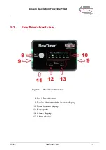
Page 13: ...FlowTimer Set 01 21 FlowTimer Set 13 5 2 FlowTimer front view Fig 5 2 FlowTimer front view 8 Set Reset button 9 Device illuminated rim status display 10 Flow duration display 11 Nameplate 12 Check display 13 Alarm display ...

Page 14: ...description FlowTimer Set 01 21 FlowTimer Set 14 5 3 FlowTimer rear view Fig 5 3 FlowTimer rear view 14 I O connection 15 Solenoid coil 16 Serial number 17 Pressure sensor connection 18 Power supply connection ...

Page 15: ...If this is exceeded a pressure reducer must be installed upstream of the FlowTimer in the direction of flow Existing KFR valves backflow preventers or check valves must be tested for function and tightness and replaced if necessary All consumers must be checked for visible leaks and repaired or replaced as necessary prior to installation If a water heating system with an expansion vessel is instal...

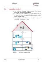
Page 16: ...e pipeline section and consumer to be monitored A backflow preventer or KFR valve must be installed upstream of each FlowTimer Normally this valve is already present behind the water meter However if several FlowTimer are used like fuses each FlowTimer requires such a valve Fig 6 2 1 FlowTimer installation EFH ...

Page 17: ...Installation 01 21 FlowTimer Set 17 Fig 6 2 2 FlowTimer installation MFH ...

Page 18: ...t allow the control electronics 6 with solenoid coil 15 to be mounted and dismounted The shut off valve may only be screwed into the pipeline at the flange connections using an open end wrench First install the shut off valve 2 and the pressure sensor 5 Observe the cable lengths and the visibility of the front of the FlowTimer when installing the valve and pressure sensor The FlowTimer electronics...

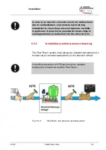
Page 19: ... it must not be possible for metal chips or sealing materials to be flushed into the valve interior 6 3 2 Installation position pressure boosting The FlowTimer system must always be installed downstream of a booster set or domestic waterworks in the direction of flow A backflow preventer or KFR valve must be installed between the booster set and the FlowTimer Fig 6 3 2 FlowTimer and pressure boost...

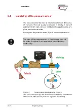
Page 20: ...lves or installed in the pipeline using a T piece with a reduced outlet Only tighten the pressure sensor 5 with an open end wrench The body of the pressure sensor or the plug area must not be turned by means of e g water pump pliers danger of destruction Fig 6 4 1 Pressure sensor installation after the valve The pressure sensor 5 can alternatively be installed Downstream of the house filter and or...

Page 21: ...be greater than 1 bar If you use a filter and or a softening system we strongly recommend to monitor them directly for water leakage using FlowTimer Detect V2 In the event of a fault the water supply is then immediately interrupted Fig 6 4 2 Pressure sensor installation after filter regulator ...

Page 22: ... on the shut off valve place the solenoid coil 15 on the armature tube of the valve 7 Then press briefly and firmly on the top of the solenoid coil not on the electronics until the coil audibly engages in the holder The coil is now correctly mounted To disassemble insert one or two screwdrivers between the valve body 2 and the solenoid coil 15 Then lever the coil away from the valve body This requ...

Page 23: ... be plugged in one position Connect any accessories to the I O port 14 of FlowTimer see the accessory manuals for more information Plug the power supply unit into a suitable socket and connect the power supply unit to the voltage supply connection 18 of FlowTimer The plug in power supply unit 1 and the solenoid coil 15 may heat up considerably during operation depending on the ambient temperature ...

Page 24: ...r in the hot water supply e g in the hot water storage tank can lead to scalding due to hot water running on in the event of the cold water supply being interrupted Unplug the power supply of FlowTimer from the wall socket Establish water supply Vent and inspect cold and hot water piping including hot water heater and heat exchangers Check consumers again for visible leaks paying attention to trac...

Page 25: ...pply The status display of FlowTimer shows red At the moment of interruption a run on from the hot water circuit must not be detectable CAUTION There is a risk of scalding if hot water runs down Disconnect the power supply to the FlowTimer to prevent possible shut off A specialist must check the installation The system is not operational until clarified If the hot water leakage is due to the syste...

Page 26: ...sed max 10 sec until the status display flashes green yellow and the Check display flashes yellow The system is now in test mode see also chapter 9 1 4 Observe whether the status display after the green yellow Flashing after max 5 minutes then shows green If the status display shows green the system is tight Please press the reset key once briefly to return to normal operation Now do the test and ...

Page 27: ... The system is now in test mode see also chapter 9 1 4 Observe whether the status display after the green yellow flashing after max 5 minutes then displays yellow If the status indicator shows yellow the leak in the overall system has been correctly detected Please press the reset button once briefly to return to normal operation WARNING If the status display does not show yellow the following fur...

Page 28: ... the current time Now observe whether the status display changes from green to red after approx 20 min and the water supply is shut off If the status indicator shows red the pauseless water withdrawal has been correctly detected Please press the reset button once briefly to return to normal operation WARNING If the status display shows green despite water withdrawal there is a fault Make sure that...

Page 29: ...ng status can be seen via the device illuminated rim 9 see chapter Fehler Verweisquelle konnte nicht gefunden werden Fehler Verweisquelle konnte nicht gefunden werden and the flow duration display 10 Should the FlowTimer interrupt the water supply during normal operation fault identification is possible via the status display 9 1 2 Restarting the system Briefly press the Set Reset key 8 or Unplug ...

Page 30: ...t therefore be restored immediately Tips A smartphone with an alarm app or power failure app can be used to monitor the mains supply which alerts via Wifi or GSM In case of poor power security e g abroad we recommend to connect a small inexpensive UPS uninterruptible power supply from the PC accessories market in front of the FlowTimer set By means of a radio controlled socket with feedback a sock...

Page 31: ...individual steps of the various tests are described under Point 8 explained but in general the FlowTimer is always put into test mode as follows Briefly press the Set Reset key 8 once Then press and hold the Set Reset key 8 again max 10 sec until the status display flashes green yellow and the Check display also flashes yellow The FlowTimer is now in test operation To return to normal operation af...

Page 32: ...ired flow duration is shown on the display 10 Then wait until the flow duration indicator 10 stops flashing The new flow duration is now stored and will be displayed again after a restart or power failure After a flow duration of 120 min all stages are displayed simultaneously This corresponds to an infinite flow duration An infinite flow duration is indicated by a running light in the flow durati...

Page 33: ...tion The result and the display of the tightness measurement remain unaffected The FlowTimer is preset at the factory with maximum sensitivity level 20 If leakage must be tolerated in your application due to the system size or type of installation you can change the sensitivity of FlowTimer in 6 steps as follows Disconnect the plug in power supply 1 and wait 30 seconds Press and hold down the Set ...

Page 34: ...is now saved Sensitivity level 20 is the highest sensitivity and level 120 corresponds to the lowest sensitivity the system tolerates greater water flow The sensitivity can only be adjusted as long as the status display is also flashing green red Immediately following the setting of the sensitivity a possible change of the flow duration see also chapter 9 1 5 is indicated when the status display i...

Page 35: ...or more information see section 10 2 2 Status display permanently yellow Yellow flashing Green flashing The test mode is currently active for more information see Chapter 9 1 4 Test mode The water supply was automatically interrupted by FlowTimer Red duration Permanent water withdrawal or leakage that has exceeded the preset maximum flow duration 30 min ex works and the tolerance limit sensitivity...

Page 36: ... poor power security e g abroad a small inexpensive UPS from the PC accessories market can be connected upstream of the FlowTimer set for additional security 10 1 No display If FlowTimer does not display a status make sure that the power supply is working and that the plug in power supply unit is plugged in If there is still no display restart the system Unplug the power supply and wait approx 30 ...

Page 37: ...on Malfunctions are particularly common in new or older installations 10 2 1 Status display permanent red The water supply was automatically interrupted by FlowTimer Red duration The preset maximum permanent flow duration has been exceeded Large leak possible Sensor breakage sensor plug incorrectly screwed to sensor Mains pressure briefly below 1 bar External accessories have triggered the shut of...

Page 38: ... the pressure range of the water Water with high pressure could escape Check if water has been used for a long period without interruption If a longer permanent flow duration is required the system can be specifically adapted to your application please refer to chapter 9 1 5 Changing the flow duration If no prolonged water withdrawal is known the piping system must be tested for tightness see chap...

Page 39: ...over a long period of time with short interruptions Were there any persons present Are there multiple slow dripping faucets if applicable Do the solenoid valves of dishwashers and washing machines really close tightly Do you find drips forming on the faucets Carefully check all water leakage points Look for traces of lime e g in the toilet Persons were not present Dripping end users are not detect...

Page 40: ...ut off cocks in order to also check the end devices or fittings for leaks WARNING Do not attempt to force open or close stuck calcified fittings The risk of destruction of the fitting including an unintentional water leakage is very high Very rarely moved and old fittings can also cause small leaks after closing and opening This also necessarily check after a time If the leak cannot be found close...

Page 41: ...atch the water meter at the same time If one of the pointers turns or the digital counter shows a short water withdrawal water could escape from the system somewhere during the waiting time You can continue to try to find the leak or hire a specialist company Alternatively you can wait to see if you notice anything else over the next few days as the leak is very small and therefore does not requir...

Page 42: ...ned Residues of sealing tapes or chips from connectors may have entered the valve during installation A qualified person can disassemble and inspect the valve by opening the four Allen screws without voiding the warranty Please note the pressure spring and the two O rings when opening To better detect possible foreign bodies when opening the valve it is best to drain the residual water through a w...

Page 43: ...despite water flow Green duration The status display remains permanently green even though water has been flowing continuously for longer than set The status display remains permanently green after test 8 3 Verification of leakage If the leakage is not indicated and there is a central hot water supply please temporarily turn off the valve in front of the boiler and the safety group and do the test...

Page 44: ...n of leakage After the check please open the KFR valve again immediately to prevent the system from running empty via the simulated leak If a leaking system is now indicated you should have the shut off valve of the FlowTimer cleaned Residues of sealing tapes or chips from connectors may have entered the valve during installation WARNING The system must first be disconnected from the power supply ...

Page 45: ...loth into a bucket see also https www youtube com watch v f5uo0P4UyfE The video is in English but shows very well the individual steps even without language skills please note Do not execute point 1 because the FlowTimer electronics can not be separated from the coil If leakage is still not indicated according to chapter 8 3 Verifying the tightness please contact our customer service at info use t...

Page 46: ...he Set Reset button After that the water supply is shut off The status display shows green permanently The pressure sensor was installed in the water flow direction upstream and not downstream of the FlowTimer shut off valve see also point 6 4 Installation of the pressure sensor If there is no incorrect installation please take pictures of your installation and send them to our customer service in...

Page 47: ...self automatically Recommissioning after longer standstill After a longer standstill an inspection must be carried out by a specialist Interval Action Weekly Visual inspection of the status display see chapter 9 2 Status display Monthly Restart the system and check the function see chapter 8 2 Checking the tightness Biennial FlowTimer should be checked by an installer after two years at the latest...

Page 48: ...ystem is not to be used for a longer period of time Unplug power supply Recommissioning A function test must be carried out when the device is put back into operation Start with point 8 2 Checking the tightness and then work your way through each of the subsequent tests and checks The FlowTimer system is no longer required Completely remove the FlowTimer system to avoid the possibility of interfer...

Page 49: ...rom moisture and dirt in shockproof packaging Avoid exceeding or falling below the permissible storage temperature Protect electrical connections from damage with protective caps The system must be transported or stored in the packaging provided until installation Incorrect storage can cause damage to the system Store the system in a dry and dust free place Storage temperature 30 C to 60 C ...

Page 50: ...c Equipment Act ElektroG Please dispose of old devices as required by law at a municipal collection point or return them to your local retailer free of charge Disposal in household waste is expressly prohibited according to the old equipment ordinance Devices received from us can be returned to us free of charge after use by sending them back with sufficient postage to the address given in the imp...

Page 51: ...riction of the use of certain hazardous substances in electrical and electronic equipment The usetech GmbH Tanzplatz 10 D 55130 Mainz declares that Product name Flowtimer Type V4 2 Year of manufacture 2017 complies with the provisions of the above mentioned EC Directives The following standards and technical specifications have been applied DIN EN 61326 1 VDE 0843 20 1 2013 07 Date 31 07 2017 Name...

Page 52: ...Declaration of Conformity Pressure Sensor 01 21 FlowTimer Set 52 15 Declaration of Conformity Pressure Sensor ...

Page 53: ...Declaration of conformity valve 01 21 FlowTimer Set 53 16 Declaration of conformity valve ...

Reviews: