background image

7

1000033245-00

4. Instructions for use

  Important

1. When preparing an AC adapter on your own, use a transformer type

unit that can stably supply 3.15 V/50 mA.
If a switching type AC adapter is used, the unit may be affected by
noise.

2. When the load is small with respect to the capacity, a voltage that is

higher than the rated voltage is output by the AC adapter that is a cause
of erroneous operation, failure, and breakage of this irradiance meter.
Confirm with data for the adapter to make selection for use.

3. For the polarity of the plug, select a device that has positive on the

center.

4. When using an AC adapter while leaving batteries in the unit, turn the

power supply off before selecting the [power supply select switch].
Changing of the [power supply select switch] with the power supply on
is a cause of error and/or failure.

4-1-3. Setup and Exchange of the Photodetector

Through exchanging the photodetector of the UIT-201, various wavelength ranges of
UV light can be measured.

 Setup of the photodetector

(1) Check to make sure that the power supply is off.

(2) Insert the connector of the photodetector into the sensor connector of the irradi-

ance meter.

 Removal of the photodetector

(1) Check to make sure that the power supply is off.

(2) Hold onto the body of the connector for the photodetector and pull it straight

out.

Summary of Contents for UIT-201

Page 1: ...USHIOINC System Company...

Page 2: ......

Page 3: ...avy injury or death Sections that display this are content where Failure to heed could lead to injury or physical damage This is noted for items concerning operation and main tenance of the equipment...

Page 4: ...ated by our company Important The measurement capability of this irradiance meter is up to 1999 however for cases where light is high power the linearity of the photodetector worsens Depending on the...

Page 5: ...This may cause an error or failure The sensitivity of this photodetector is calibrated using monochromatic light Multiple photodetectors of the same type provide the same indication for mea surement...

Page 6: ...iv 1000033245 00...

Page 7: ...teries 6 4 1 2 Using the AC Adapter 6 4 1 3 Setup and Exchange of the Photodetector 7 4 2 Measurement Method 8 4 2 1 Turning unit on 8 4 2 2 Turning unit off 8 4 2 3 Adjustment of sensitivity 8 4 2 4...

Page 8: ...meter is small and lightweight and as the measurement is indicated using a digital display using mW cm2 units measurement can be made easily and without error at the worksite In addition the irradianc...

Page 9: ...ly UIT 201 UIT 201 unit 2 m extension cable 2441 7711 AC adapter 6003 3042 Photodetector UVD 365PD UVD 405PD etc Operating manual Analog signal output cable 1 5 m 2441 7687 Connector model HR10 7P 6P...

Page 10: ...1000033245 00 4 Instructions for use 3 Names for each of the Sections 1 8 10 9 19 18 7 5 6 14 13 15 12 11 16 4 3 2 17 Analog signal output cable Photodetector Main unit 3 Names for each of the Section...

Page 11: ...s when L range is selected while irradiance is being measured The display lights indicated by 8 10 all blink while in sensitivity adjustment mode 11 H M L switch Used for selecting the measurement ran...

Page 12: ...put the batteries into the unit 1 Remove the battery cover on the rear surface of the unit 2 Insert 3 AAA batteries according to the direction indicated on the irradiance meter body 3 Replace the batt...

Page 13: ...has positive on the center 4 When using an AC adapter while leaving batteries in the unit turn the power supply off before selecting the power supply select switch Changing of the power supply select...

Page 14: ...ly 1 second Numbers on the display monitor disappear The power is turned off 4 2 3 Adjustment of sensitivity After turning the UIT 201 on it starts up in H range irradiance sensitivity measure ment mo...

Page 15: ...tor reading is 2 or less 5 After setting with unit set up so that light can not get to the photodetector press the switch again Perform zero correction for the new sensitivity sensitivity Here is indi...

Page 16: ...ng 1 Connect the analog signal output cable that came with the unit to the analog signal output terminal Connect the orange and white wires of the analog signal output cable respec tively to the termi...

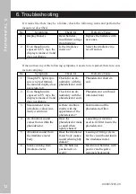
Page 17: ...Abnormal battery voltage error The battery level has run low Turn off the power and replace the battery cells with new ones System down error The CPU may have failed Turn off the power and turn it on...

Page 18: ...ays the display remains at 0 and does not change Check for an ab normality with the photodetector cord Photodetector cord break disconnection 3 Measurement value irradiance value sud denly went down I...

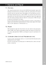
Page 19: ...ment free of charge However this instrument is not covered by warranty I fit is used in a wrong manner a manner not described in the operation manual or in the careless manner if it is modi fied or if...

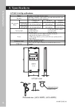
Page 20: ...405PD 120 1500 A W cm2 199 9 mW cm2 0 001 mW cm2 Analog output Output voltage Output impedance Response speed 1 999V for full scale output Less than 2 k Roughly 50 msec Power 3 AAA batteries or an AC...

Page 21: ...Note 1 Angular dependency Common between models Photodetector Specifications 8 Specifications Spectroscopic sensitivity 300 400 nm Wavelength 400 500 nm Wavelength Spectroscopic sensitivity 30 0 60 9...

Page 22: ...on is performed by other than USHIO Failures where cause is other than product from USHIO such as software de sign content or the customer s equipment etc Failure caused by external factors for which...

Page 23: ......

Page 24: ...USHIOINC URL http www ushio co jp...

Reviews: