Page 11
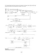
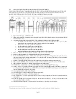
The bottom section of figure 4.2a shows what a typical analog output looks like. The appropriate DSP drives a
digital to analog converter, which then drives the output trim controls, which then drives the balanced line driver.
The output is disconnected when the system is muted. Separate bypass audio circuitry is switched to the output
when bypass is enabled. Output module circuitry measures the actual audio level on the outputs for presentation
on the front panel bargraph.
The following figures show the details of the crossovers. In most installations, the user merely loads crossover
settings from the supplied speaker library, and then adjusts the output trims as required to compensate for
amplifier gain differences and speaker efficiency differences.
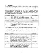
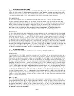
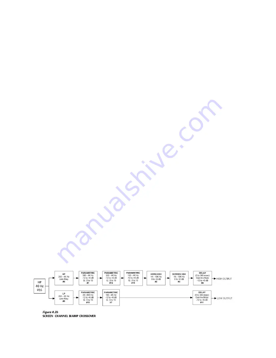
Figure 4.2b shows a typical biamp crossover for a screen channel. This crossover is available if a 16 channel or
larger output module is installed. The audio leaving the graphic equalizer drives a high pass filter (filter #16). The
cutoff frequency and the Q can be adjusted by the user. The audio is then split into high band and low band
components with high pass filter #0 and low pass filter #9. These are both 4th order Linkwitz-Riley filters. These are
followed by a series of parametric filters. The high band includes a pair of shelving filters (#2 and #3) to
compensate for the high frequency characteristics of the high frequency horn and the screen. Each band ends up
with a delay block. Individual band delays can be set as required to get the high and low frequency acoustic signals
in phase. This block also includes a provision to flip the phase in case a speaker is wired incorrectly. The delay block
also has adjustable gain, though this gain is normally set to 0dB. When using an analog output module, band gains
are adjusted using the output trim shown in the bottom section of figure 4.2a. Use of this analog control instead of
a digital control provides the widest possible dynamic range. If an AES output module is installed, the band output
trim is handled by the delay block since no analog trim is available.
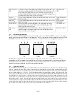
Figure 4.2c shows a typical triamp crossover for a screen channel. The details are very similar to the biamp
crossover of figure 4.2b except that the channel is split into three bands.
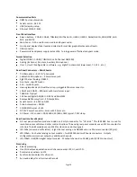
Figure 4.2d shows the LFE "Crossover." It is not really a crossover since it does not split the channel into multiple
frequency bands. It is similar to a crossover, however, in that a single audio channel is split into multiple outputs
and separate equalization (parametric) and delay can be applied to each output. Because of this similarity, the LFE
equalizer is located in the crossover section of the DSP and in the "XO, etc." tab on the GUI. The multiple LFE
outputs are only available on output modules with enough outputs, but the LFE equalization is always in the "XO,
etc." tab on the GUI. For convenience, the LFE parametric equalizer settings are shown in both the Equalizer and
XO, etc. tabs in the GUI.
Figure 4.2e shows the Ls "Crossover." The Rs “Crossover” is identical. Similar to the LFE, this is not a true crossover
since it does not split the channel into frequency bands. It does, however, split a channel into multiple outputs
with individual delays, similar to a crossover. For that reason, the "XO, Etc." tab on the GUI contains delay and gain
settings for multiple Ls/Rs outputs. The Surround Outputs tab has level adjustments and surround delays for
individual surround channel pairs. These can be thought of as "master" level settings and delays with individual
level and delay settings available for Ls and Ls1 outputs (and similarly for Rs). The total delay is the sum of the
delay shown on the Surrond Outputs tab and the delay on the "XO, etc." tab.
Summary of Contents for JSD-100
Page 12: ...Page 12...


