Page 40
4.
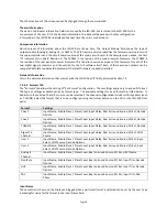
Adjust the frequency control to the worst dip or peak in the LFE portion of the RTA display.
5.
Set the Q to 4 and adjust the PEQ gain as required to remove the peak or dip. The Q can be increased to
make the peak or notch narrower, or decreased to make it wider. The frequency can be adjusted as
required to center the peak or notch on the notch or peak displayed on the RTA.
6.
If desired, the HP filter to the left of the parametric filters can be adjusted to add a bit more low
frequency range. Try increasing the Q above the default 0.707, then adjust the frequency as required to
yield a flatter LFE response. A Q above 0.707 adds a peak at the filter cutoff frequency before the rolloff
begins.
7.
If there is a notch in the transition region between the LFE and center channel frequencies, try reversing
the phase on the LFE channel (Invert button on the Stage Out tab).
8.
Finally, adjust the leftmost gain control up to increase the LFE output as required. SMPTE RP 200-2002
calls for LFE to be 10dB above the center channel, but this may be excessive in some auditoriums.
9.
If the JSD-100 has multiple LFE outputs, the individual PEQ controls can be adjusted similarly.
Summary of Contents for JSD-100
Page 12: ...Page 12...


