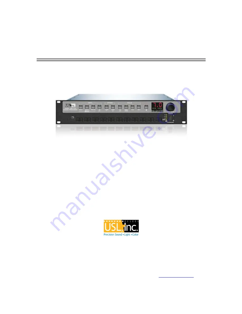
background image


JSD-100MA Manual 


Cinema Processor  


USL, Inc. 

181 Bonetti Drive 

San Luis Obispo, CA  93401-7397 

USA 

Phone:  +1 805 549 0161     Fax:  +1 805 549 0163     

www.uslinc.com


Summary of Contents for JSD-100MA

Page 1: ...JSD 100MA Manual Cinema Processor USL Inc 181 Bonetti Drive San Luis Obispo CA 93401 7397 USA Phone 1 805 549 0161 Fax 1 805 549 0163 www uslinc com...

Page 2: ...8 4 3 Channel Descriptions 11 4 4 Sound Field Configurations 12 4 5 Processing Channels 12 5 SPECIFICATIONS 13 5 1 Features 13 5 2 Audio Inputs 13 5 3 Sixteen Channel Analog Audio Outputs JSD 100MA 1...

Page 3: ...8 6 6 4 RS 485 18 7 GRAPHICAL USER INTERFACE CONFIGURATION 18 7 1 System Configuration Using the Graphical User Interface 18 7 2 GUI File Organization 18 7 3 Windows JSD 100MA Installation 19 7 3 1 Wi...

Page 4: ...Page 4 9 JSDV 100 REMOTE VOLUME CONTROL 40 10 PRODUCT SUPPORT 41 APPENDIX A CONNECTOR PIN OUTS 41 APPENDIX B AUTOMATION COMMANDS 45 APPENDIX C SYSTEM RESTORE AND POWER UP BUTTONS 46 APPENDIX D INI FI...

Page 5: ...on Keep product surfaces clean and dry Disconnect the power cable from the power source before cleaning Do not use liquid cleaners or aerosol cleaners Use a damp cloth for cleaning Do not push objects...

Page 6: ...Requirements CE UL cUL Safety and Overall Compliance VDE Certified Power Cords Pollution Not intended for environments where conductive pollutants may be present 2 2 Equipment Class Type A Equipment t...

Page 7: ...other equipment while simultaneously being monitored over another TCP connection The Graphical User Interface runs on Windows XP Windows 7 Windows 8 and Windows 10 operating systems It allows for comp...

Page 8: ...metric equalizer and a 125Hz low pass filter as specified by SMPTE EG0432 2 2006 Similarly the surround channels go through a graphic equalizer Provision is made to select the source of the surround c...

Page 9: ...this gain is normally set to 0dB band gains are adjusted using the output trim shown in the bottom section of figure 4 2a Use of this analog control instead of a digital control provides the widest p...

Page 10: ...Version 160624 Page 10 Figure 4 Screen Channel Biamp Crossover Figure 5 Screen Channel Triamp Crossover Figure 6 LFE Channels...

Page 11: ...room Subwoofer SW Left Side Front Lsf Located on the left side at about 1 2 the distances from the screen and before the surround speaker array located at about 1 3 the distance from the front Right...

Page 12: ...Processing Channels The JSD 100MA has 16 processing channels Each of these receives audio from a variety of sources The processing channel includes the main fader control equalization synchronization...

Page 13: ...el Analog Audio Outputs JSD 100MA Sixteen Channels Balanced 300mV adjustable outputs that can be configured as 5 1 7 1 13 1 15 1 broadband biamp or triamp 5 4 Communication Ports DB25F pulse automatio...

Page 14: ...on systems with 16 or more outputs Crossovers support biamp and triamp of up to five screen channels plus individual parametric equalization on one to three LFE outputs Crossover includes a speaker l...

Page 15: ...format button LEDs for digital formats will flash when no digital input is provided Press the mute button verifying that its LED toggles each time the button is pressed Rotate the fader in each direc...

Page 16: ...s L and R analog inputs 15 RTA microphone 3 5mm stereo jack with 10V on the ring designed for use with a powered electret microphone 16 8 Channel Analog Input on DB25F Balanced line inputs Six channel...

Page 17: ...t of the automation commands 6 6 1 Parallel Interface Pins 1 through 10 of the DB25F automation connector are control pins that accept contact closure or open collector pulses to ground to select form...

Page 18: ...nfiguration 7 1 System Configuration Using the Graphical User Interface The graphical user interface GUI allows for configuration and monitoring of the JSD 100MA When the application has been installe...

Page 19: ...e drivers being installed on the computer require selecting a mode that will bypass the signing requirement via the Advance Startup Options In addition to accessing the startup options Bit Locker must...

Page 20: ...up arrow an installation icon may appear in the task bar near the tray items such as network connection status The driver will be ready for use once the installation completes As another alternative D...

Page 21: ...t on either the JSD 100MA unit or on the GUI and both will reflect the new value If you open a configuration file when connected to the JSD 100MA all the settings in that configuration file are sent t...

Page 22: ...d the next time the JSD 100MA is powered up If Save To SD Card is checked the configuration will be saved to both the SD card and the flash memory when the Save Changes button is pressed If Save Chang...

Page 23: ...ve the settings when disconnecting from the JSD 100MA 7 5 2 5 4 SD Card Backup Pressing this button writes the current configuration to the SD or MMC card plugged in behind the removable panel on the...

Page 24: ...rmware version identifies the firmware version in two of the microcontrollers and the circuit board revision of the main circuit board In the sample screen above the first F indicates this is main boa...

Page 25: ...the user Type a meaningful name for the format in the Input Name field 7 5 5 2 4 EQ Set The JSD 100MA allows different formats to use different equalization curves Four EQ sets are available Each EQ...

Page 26: ...b The JSD 100MA equalizer allows the frequency response of the JSD 100MA to be adjusted for the acoustics of the room The RTA screen shows the measured sound pressure level SPL the measured level in e...

Page 27: ...tor Press the Generator button to turn the generator on or off Use the adjacent Pink 100Hz 1kHz 10kHz and Sweep buttons to select the type of generator output Auditorium equalization typically uses pi...

Page 28: ...he channel name text can be edited to reflect labels and or acronyms as required for installation 7 5 5 4 2 Channel Output Trim For each channel the output trim control has an adjustment range of 3dB...

Page 29: ...le time zones The Date and Time dialog allows setting of date and time data for the JSD 100MA Since the JSD 100MA uses UTC time the displayed time is UTC If the system is using an NTP server you do no...

Page 30: ...nge a level change or a specific command over Ethernet See Appendix B Audio presence will not wake the system up since the audio circuitry is shut down during sleep The current sleep timer value is sh...

Page 31: ...se generator then disable it Enabling the internal pink noise generator configures the internal RTA for proper operation The Speaker button opens a file select dialog where you can select a speaker fr...

Page 32: ...gs for an LFE output Depending on the output module type one or more LFE outputs are available Each has a separate parametric equalizer that can be adjusted on this screen Similarly Ls and Rs may have...

Page 33: ...Tab The firmware in the main processor and the Digital Signal Processors DSPs in the JSD 100MA can be updated through the GUI over Ethernet or USB The right side of the screen shows the current firmwa...

Page 34: ...the power amplifier gains all the way down 6 Set the JSD 100MA fader to 7 0 7 Under the XO Etc Tab press the Speaker button and select the desired speaker from the speaker library 8 Under the Stage Ou...

Page 35: ...tton to bring up the microphone calibration dialog box i Adjust the Microphone Gain control in the microphone calibration dialog box until the XSP SPL agrees with the reference SPL meter j If desired...

Page 36: ...the leftmost Gain control is the master LFE gain that applies to all LFE outputs It corresponds to the LFE gain control shown on the Stage Out tab Within each LFE box is another gain control that appl...

Page 37: ...ypass operation 16 Fader Controls the overall volume of all the channels 8 1 Front Panel The input select buttons choose which input is to drive the auditorium speakers The LED above the button will l...

Page 38: ...rear panel automation connector Pulsing pin 1 to ground is the same as pushing the first button on the front panel COAX 1 Pulsing pin 2 to ground is the same as pushing the second button The parallel...

Page 39: ...eb server can be used to view the current status of the JSD 100MA view the JSD 100MA log and upload new firmware The Status Page shows the current fader level the current format and a bar graph showin...

Page 40: ...y will normally start flashing immediately but it could take up to two minutes for them to start flashing When they stop flashing the factory installed firmware has been restored and the JSD 100MA wil...

Page 41: ...to the cable adjacent to the connector to comply with FCC and CE emission requirements Audio Channels AES Pair JSD 100MA Pin out shield Speakers 1 2 1 24 12 25 L R 3 4 2 10 23 11 C LFE 5 6 3 21 9 22...

Page 42: ...erminals drive the auditorium amplifiers or crossover The corresponding Phoenix strips and DB25M connectors are connected together within the JSD 100MA The DB25M connectors use the same THX pin out as...

Page 43: ...pulls pin 24 low when the system is muted Pins 1 through 11 are internally pulled up to 8 4V They each source 400uA when grounded A pin needs to be pulled below 2 6V for 10ms or more for the JSD 100MA...

Page 44: ...ally connected to pins 4 and 6 Does not need to be connected in most cases 2 TXD The JSD 100MA transmits data on this pin 3 RXD The JSD 100MA receives data on this pin 4 DTR Internally connected to pi...

Page 45: ...2 of the 9 pin D connector The JSD 100 receives data on pin 3 Communications is at 38 4kbps 8N1 8 data bits no parity 1 stop bit Ethernet The JSD 100 listens on port 10001 for TCP connections from oth...

Page 46: ...JSD 100MA need to be replaced all the saved settings from the old unit can be easily loaded in to the new unit without the use of a computer These settings were saved during the initial configuration...

Page 47: ...60 0 ChannelGain 20 0 Fader 7 0 EQSPL 80 0 Decay 100 This state is used for setting up the settings prior to running the automatic EQ procedure An average is created within a valid range of the distri...

Page 48: ...5 0 This is used for controlling which bands will be updated by the automatic EQ process A 1 or 0 is used to enable or disable a band for automatic EQ BandsToEQ Bass 1 Band40 1 Band50 1 Band63 1 Band...

Page 49: ...z Value 1 Max 2 Min 6 Band50Hz Value 0 Max 3 Min 5 Band63Hz Value 0 Max 3 Min 4 Band80Hz Value 0 Max 3 Min 3 Band100Hz Value 0 Max 3 Min 3 Band125Hz Value 0 Max 3 Min 3 Band160Hz Value 0 Max 3 Min 3 B...

Page 50: ...Max 3 Min 3 Band1 6kHz Value 0 Max 3 Min 3 Band2kHz Value 0 Max 3 Min 3 Band2 5kHz Value 1 Max 2 Min 4 Band3 15kHz Value 2 Max 1 Min 5 Band4kHz Value 2 5 Max 0 5 Min 5 5 Band5kHz Value 3 5 Max 0 5 Min...

Page 51: ...ported from the JSD 100MA The RTA display will reflect the response and is also reflected in the Auto EQ execution A positive value will increase the RTA display level for that band Response Band25 0...

Page 52: ...req 40 PEQ1Q 1 0 PEQ1Gain 0 0 Mid Band HPFreq 260 LPFreq 1600 Gain 2 5 Delay 0 1 PEQ1Freq 800 PEQ1Q 1 0 PEQ1Gain 0 0 PEQ2Freq 6000 PEQ2Q 1 0 PEQ2Gain 0 0 High Band HPFreq 1400 Gain 5 0 Delay 0 0 PEQ1F...

Page 53: ...Version 160624 Page 53 Revision History 160624 First release...

Reviews: