


Version 160624
Page 42
Eight Channel Analog Input
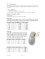
The JSD-100MA eight channel analog input is on a DB25F connector. The analog inputs are active balanced
(differential) inputs. They may be driven by balanced or unbalanced sources. When driven by an unbalanced
source, the negative input should be connected to the low side of the source at the source equipment to
minimize ground loop noise. The cable should be twisted pair with individual shields, even when driven by an
unbalanced source. A USL supplied ferrite block should be clipped around the cable to Ensure FCC and CE EMI
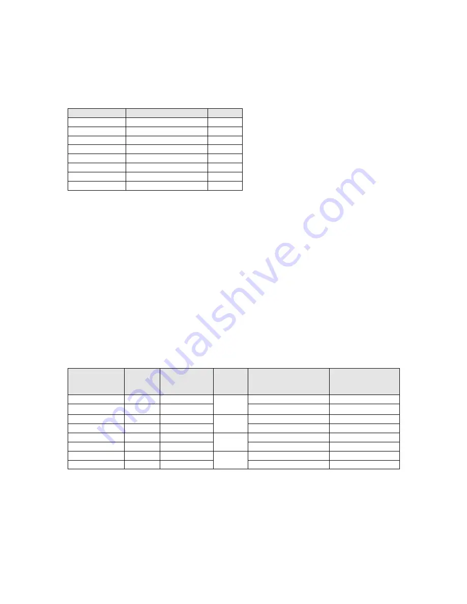
requirements are met. The DB25F connector uses the THX® pin out as specified in the table below.
Channel Number DB25F PINS ( +, -, shield ) Speakers
1
2, 14, 1
Left
2
8, 20, 7
Right
3
5, 17, 4
Center
4
25, 12, 13
LFE
5
23, 10, 22
Lss
6
24, 11, 9
Rss
7
16, 3, 15
LH
8
19, 6, 18
RH
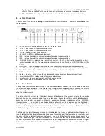
Sixteen Channel Analog Audio Outputs
The main outputs drive a pair of Phoenix connectors, and a pair of DB25M connectors. The Phoenix output
terminals are marked “Main Outputs” and “Optional Outputs.” The DB25M connectors are marked “Monitor 1
Outputs” and “Monitor 2 Outputs.” The DB25M connectors typically drive a booth monitor, while the Phoenix
terminals drive the auditorium amplifiers or crossover. The corresponding Phoenix strips and DB25M
connectors are connected together within the JSD-100MA.
The DB25M connectors use the same THX® pin out as the eight channel analog input. The USL supplied ferrite
block should be clipped on to the cables adjacent to the connectors to comply with FCC and CE emission
requirements. The “optional outputs” can be configured as additional full range channels (for example, for 16
channel output), or may be configured as the outputs of the internal crossovers.
Note that the 16 channel analog output module supports crossovers. To allow for proper bypass operation, a
passive crossover is included. For full band operation, set all four DIP switches to OFF and set the MID and
HIGH trim pots to full counter-clockwise. Adjust the LOW trim pot for the desired full range bypass audio level.
See section 7.5 for more information on adjusting the bypass crossover. Remember that the front panel fader
also affects output level when in bypass.
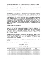
Rear Silk Label
(Main)
Channel
Label
Full Range
Audio Channel
AES
Pair
Phoenix Main Output
Pins (+, -, shield)
DB25M Monitor 1
Output
Pins (+, -, shield)
L+ L-
L
1
1
1, 2, 3
2, 14, 1
R+ R-
R
2
6, 7, 8
8, 20, 7
C+ C-
C
3
2
4, 5, 3
5, 17, 4
LFE+ LFE-
LFE
4
9, 10, 8
25, 12, 13
Ls+ Ls-
Lss
5
3
11, 12, 13
23, 10, 22
Rs+ Rs-
Rss
6
14, 15, 13
24, 11, 9
+Lrs-
LH
7
4
16, 17, 18
16, 3, 15
+Rrs-
RH
8
19, 20, 18
19, 6, 18


