


Page 17
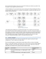
block. Individual band delays can be set as required. This block also includes a provision to flip
the phase in case a speaker is wired incorrectly.
In most installations, the user merely loads crossover settings from the supplied speaker library,
and then adjusts the output trims as required to compensate for amplifier gain differences and
speaker efficiency differences.
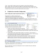
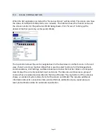
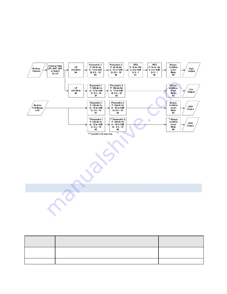
Figure 5.2c Crossover Overview
In the lower portion of Figure 5.2c, the LFE band is shown. It is not really a crossover since it
does not split the channel into multiple frequency bands. It is similar to a crossover, however, in
that a single audio channel is split into multiple outputs with separate equalization (parametric)
and delay. Because of this similarity, the LFE equalizer is located in the crossover section of the
DSP. The additional LFE2 output is available from the optional crossover board’s output
connector, the optional AES/EBU outputs, or the optional BLU link output.
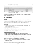
5.3
MODEL NUMBERS
An optional output board is part of the unit’s assembly that supports a variety of output
configurations. These are listed in the table below.
The various JSD-‐60 options are identified by model number suffixes as shown in the tables
below. The first letter identifies input options such as the presence or absence of Dolby Digital®
and DTS® decoding. The second letter indicates the type of output. Note that all units have
analog HI/VI-‐N in addition to the outputs listed in the tables below.
First Suffix
Letter
Description
USL Module Part
Number
L
8 channel AES/EBU input, no Dolby Digital® or DTS®
decode
N/A
D
8 channel AES/EBU input, Dolby Digital® and DTS®
DI-‐84


