

Page 26
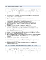
Two Channel Digital Inputs
The JSD-‐60 has an S/PDIF input and a TOSLINK input.
•
S/PDIF Input.
A stereo digital input on an RCA connector marked COAX. It is a standard
S/PDIF (Sony Philips Digital Interface) input. Connect to appropriate sources with 75 ohm
coaxial cable with RCA connectors on each end. As with the other stereo inputs, various
decode methods are available.
•
TOSLINK Input.
A TOSLINK optical digital stereo input is included on the JSD-‐60. Connect
this input to an appropriate source with a standard TOSLINK cable. As with other stereo
inputs, various decode methods are available.
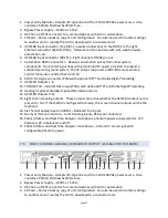
Single Channel Audio Inputs
The JSD-‐60 has a Public Address (PA) and Real Time Analyzer (RTA) microphone input.
•
PA/RTA Microphone Input.
Plug a PA microphone in to the combination XLR / ¼” stereo
(TRS) phone jack. The microphone input may be configured to drive the main or the
surround speakers. In addition, the PA microphone input can drive the RTA for room
equalization.
The jack is a combination XLR and ¼” TRS (stereo) connector. The XLR input is
balanced. The 1/4 inch connector can be used either balanced or unbalanced. Phantom
power can drive both sides of a balanced line with +12V through 1k on each line. It can also
drive an unbalanced input (typically on the 1/4 inch connector) with +9V through 1.8k.
When using unbalanced phantom power, the signal is on the tip and the phantom power
voltage is on the ring. The phantom power is designed to provide low current bias to
electret microphones. Condensor microphone preamps may draw more current than the
phantom power can supply.
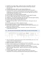
7.8
ANALOG AUDIO OUTPUT CONNECTIONS
The JSD-‐60 provides eight main channel outputs plus HI and VI-‐N outputs. All outputs are
balanced and may drive balanced or unbalanced loads. When driving unbalanced loads, run two
conductor shielded cable and connect the “ – ” terminal of the JSD-‐60 output to the low side
of the unbalanced load at the load instead of at the JSD-‐60 to minimize ground loop noise.
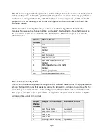
Main Audio Outputs
The eight channel analog output connector provides eight balanced analog outputs. These are
full-‐range outputs if no crossover board is installed. If a crossover board is installed, this
connector provides the low band outputs of the screen channels, the full range surround
channels, and the LFE1 output. The crossover output connector provides three crossover high
band outputs plus the LFE2 output. On systems with the crossover, four DIP switches set the
crossover frequency for the bypass passive crossover. If the crossover is not to be used, set all
the switches to off. Adjust the low trim pot to yield the desired bypass output level. Remember
that the front panel fader also affects the output level when in bypass. For more information on