Page 59
8.10.12
DIAGNOSTICS TAB
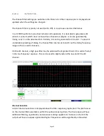
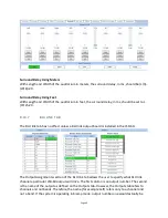
This tab provides diagnostics that help USL personnel in debugging the system. You may be
instructed by USL to perform various functions on this tab to debug problems in the installation.
The terminal section of this screen can be used to test JSD-‐60 commands, such as ones an
automation system can send. Click the mouse cursor in the terminal area, and then type
commands (tab delimited and terminated with a carriage return). See Appendix B for more
information on automation commands.
8.11 CHANNEL CROSSOVER AND EQUALIZATION PROCEDURE
Audio channel equalization consists of two steps:
1.
Crossover adjustment (if crossovers used).
2.
Channel Equalization.
8.11.1
CROSSOVER ADJUSTMENT
A suggested crossover adjustment procedure is listed below. It should be skipped if the JSD-‐60
internal crossovers are not being used. If an external pink noise generator is to be used with the
internal RTA, enable the internal pink noise generator, then disable it. Enabling the internal pink
noise generator configures the internal RTA for proper operation.
1.
Ensure that the proper speaker configuration biamp is selected by the Channel Config
button.
2.
Position the RTA microphone in the auditorium as specified by SMPTE ST 202:2010 (about
2/3 of the way back from the screen and 2/3 of the way from a side wall of the auditorium).
The microphone is normally 1.0 to 1.2 meters (3.3 to 4.0 feet) from the floor, or “ear level”
for a typical audience member.
3.
Plug the microphone in to the microphone input.
4.
On the Outputs tab, slide all the level controls to minimum level.
5.
Turn the power amplifier gains all the way down.
6.
Set the JSD-‐60 fader to 7.0.
7.
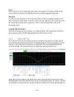
Under the Crossovers tab, press the Speaker button and select the desired speaker from the
speaker library.
8.
Under the Outputs tab, select pink noise and press the Gen button for the left channel.
9.
Turn up the amplifier gains as far as possible without exceeding 85dB SPL in the auditorium.
10.
On the Crossovers tab, press the View button to make the RTA display visible.
11.
Adjust the Data Offset control (becomes visible when the cursor is over the graph area) until
the RTA results become visible on the RTA display.
12.
Adjust the band gains as necessary for the flattest RTA response possible.
13.
If there appears to be a notch in the response at the crossover frequencies, try pressing an
Invert button to switch the phase on a band.
14.
Press Copy and copy the crossover settings to each of the other screen channels.
15.
Go back to the Outputs tab, turn off the generator on the left channel and turn it on for the
next channel. Repeat the above process for each channel.

