8
10
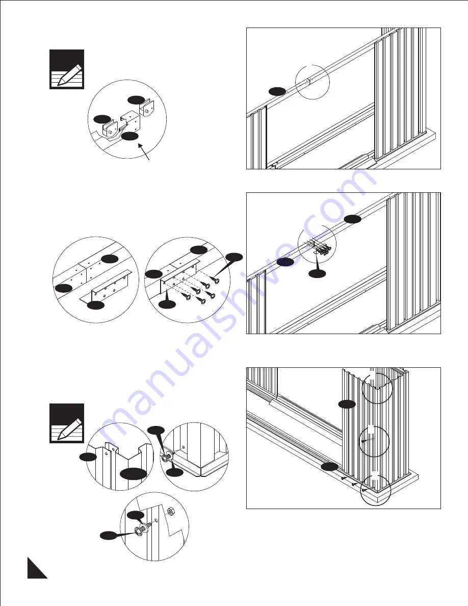
. Insert two pieces of (TS) Top slider into the
sliding channel. See blowup.
Make sure the position of
the projection on top
slider towards inside.
Note
SLA
IMPORTANT: USE HAND GLOVES TO PREVENT INJURY.
TS
TS
SLA
Front
Fig.1
1
11
. Place the sliding channel support (SSA) in
between the sliding Channels (SLA)& (SRA). Align
the holes with sliding channel and secure with (S1)
screws. See fig. 1 & 2.
S1
Fig.1
Fig.2
SLA
SSA
SRA
SLA
SRA
SSA
1 & 2
SLA
SRA
SSA
12
. Place the wall panel (WS) on the base bar (BLA).
Line up the holes with base bar. Secure with (S1)
screws with washers . See fig. 2.
Use (S3) bolt and nut with washers to join together
in the middle of the wall panel. See fig. 3.
Make sure the overlapping
position is as shown in fig.1.
Note
Fig.1
Fig.2
S1
BLA
1
2
3
Fig.3
WS
S3
PW
PW
WCFS
WS


