background image

8

USSC

For installations with horizontal through-the-wall exhaust, it is strongly recommended that the stove combustion air be

connected to the outside.  If the home is newer or has been tightly insulated it is required to install outside combustion

air.

Connection to outside the house is REQUIRED for mobile home installations.  We strongly urge use of the 67FAK Fresh

Air Kit.

Only noncombustible pipe 2 inches (or greater) in diameter is approved to use for outside air connections (straight or

flexible).  PVC pipe is NOT approved and should NEVER be used.

If the air inlet is connected to the outside, it MUST be terminated with a vertical 90-degree bend (down) or with a wind

hood.  Failure to do so could result in a burn back during high winds blowing directly up the air inlet during a simulta-

neous power failure (see diagram above).

Blockage, excessive length, or extra bends in the air intake pipe will starve the stove of combustion air.  A 90-degree

bend is equivalent in restriction to approximately 30 inches of straight inlet pipe.

DESIGN GUIDELINES FOR OUTSIDE COMBUSTION AIR CONNECTION

1)

2)

3)

4)

5)

90 DEGREE BEND TERMINATION

WIND HOOD TERMINATION

Wind Hood

2” Min. Diameter

3”

2”

6”

CAUTION:   The operation of exhaust fans such as bath room fans, attic fans, etc. might starve the heater of combustible air

creating a negative pressure in the room.  Provide adequate ventilation in the room accompanying the heater.  If not, the

pressure switch may shut off operation of the heater. (Due to negative pressure)

NOTE:

A wire mesh screen with a

maximum opening size of 3/8”

must be installed.

Downloaded from 

www.Manualslib.com


manuals search engine


Summary of Contents for 6039

Page 1: ...nd installation requirements peculiar to your area Do Not Plug this appliance into an electrical outlet before reading and understanding all operations and always unplug the unit before attempting any work or maintenance Do not connect this stove to any chimney flue already serving another appliance Carefully observe and maintain all clearances to combustibles A note about fuel Use only dried shel...

Page 2: ...ou ve purchased one of America s Finest Multifuel Burning Stoves By heating with fuels such as corn and pellets you re helping CONSERVE AMERICA S ENERGY CONGRATULATIONS BTU output will vary depending on the brand type and quality of fuel and the moisture content Consult your dealer for best results 0 Based on post 1982 home construction requiring 35 BTU Hr per Sq Ft Remember this stove should not ...

Page 3: ...urned to the outside as shown Use the four 4 10 Tek Screws provided 5 Assemble the legs using the eight 8 Bolts as shown 6 After all bolts and screws have been tightened properly set the heater back up on the legs and replace the two ash dump covers See pg 15 for ash dump cover placement 1 The Auger is packed in the hopper and must be installed properly as illustrated below 2 Insert the Auger into...

Page 4: ...periodic maintenance for proper operation and long life of the stove Read and follow the maintenance schedule closely DISCONNECT THE POWER CORD BEFORE SERVICING THIS STOVE A power surge protector is required The unit must be plugged in to a grounded 110 volt power source Circuit Boards are very expensive protect yours Always route the power cord away from the unit Do not route cord in foot traffic...

Page 5: ... to midsize kernel corn If the kernel size of the corn varies greatly or if you switch sources frequently you will get a less consistent burn Therefore purchasing corn from the same source will help achieve a more consistent burn DO NOT USE CORN WITH A HIGH WAX CONTENT WOOD PELLETS As with corn be consistent in your pellet supplier Pellets will vary in content and burn characteristics from supplie...

Page 6: ...m B Sidewall to Flue 5 in 127mm C Backwall to Flue 3 in 75mm D Backwall to Unit 9 in 228mm E Right Sidewall to Top Edge of Unit 2 in 50mm CORNER F Adjacent Wall to Flue 3 in 75mm G Adjacent Wall to Unit 4 in 100mm BACK WALL SIDE WALL SIDE WALL Backwall Sidewall Parallel BACK WALL Corner Installation NOTE Allow sufficient space to remove the left and right side panels for maintenance purposes 6 min...

Page 7: ...ees and elbows should not be mounted directly to the rear of the stove Total length of horizontal vent must not exceed 48 4ft 1 200mm The maximum recommended vertical venting height is 12 feet for 3 inch type PL vent All joints in the vent system must be fastened by at least 3 screws and all joints must be sealed with RTV silicone sealer to be airtight The area where the vent pipe penetrates to th...

Page 8: ...urn back during high winds blowing directly up the air inlet during a simulta neous power failure see diagram above Blockage excessive length or extra bends in the air intake pipe will starve the stove of combustion air A 90 degree bend is equivalent in restriction to approximately 30 inches of straight inlet pipe DESIGN GUIDELINES FOR OUTSIDE COMBUSTION AIR CONNECTION 1 2 3 4 5 90 DEGREE BEND TER...

Page 9: ...t extend a minimum of 12 inches from the outside of the building Rodent screen cannot be less than 3 8 opening mesh If installing with combustion air from outside cut a separate hole through the wall for the fresh air tube C This tube must be 2 minimum diameter pipe Connect outside air pipe inlet on stove This tube must be terminated with a 90 degree elbow or hood 1 2 3 4 5 6 FREESTANDING STOVE IN...

Page 10: ...mum Vertical Pipe Dimensional tolerance 0 25 12 1 8 11 3 4 10 1 16 EXHAUST OULET 3 DIA COMBUSTION AIR INTAKE 1 7 8 DIA 10 1 16 11 5 8 12 EXHAUST OUTLET 3 DIA COMBUSTION AIR INTAKE 1 7 8 DIA 6039 PEDESTAL UNIT 6039T LEG UNIT Downloaded from www Manualslib com manuals search engine ...

Page 11: ...ERMINATION CAP The Hearth Pad is not required under the unit if the floor is noncombustible but is required 6 inches 152mm beyond the front of the unit and 6 inches 152mm beyond each side of the door if the floor is a combustble floor wood flooring carpet linoleum etc NOTE Vertical Pipe must be 4 PL Above 4 Downloaded from www Manualslib com manuals search engine ...

Page 12: ...te unit with broken glass Do not substitute original factory glass You must use only factory authorized glass Do not slam door shut Do not strike glass Do not use abrasive cleaners Do not clean when glass is hot CLEANING THE GLASS When the fire is first started it will produce some smoke The smoke might accumulate on the glass surface Before the fire gets hot open the door and wipe the glass surfa...

Page 13: ...mpletely burning in the firepot as the agitator rotates NOTE If the starting fuel is not burning hot enough you may see the fire begin to go out as new fuel is being added If this occurs pressing the C button will allow the auger to pause for 1 minute Pressing the ON button will resume the auger if 1 min is to long If not enough fuel is the reason for not burning pressing and holding the ON button...

Page 14: ...s not cleaned out it could cause the fuel stirrer to jam USSC highly recommends an additive see Fuel Additive Pg 15 be added to your corn to eliminate these clinkers Contact your local Feed and Seed for availability and cost You will need this additive if the agitator fingers develop an accumulation or build up Daily Maintenance Soot and Flyash Formation and Need for Removal The products of combus...

Page 15: ...amage the insulation Scrape the fly ash from the clean out chambers toward the front of the burn chamber Remove the fly ash from the burn chamber and replace the clean outs Remove the ash pan and dump the ash into a metal container Cleaning of the exhaust system will depend upon the ash and debris content of your fuel If your fuel has a high ash content and or significant debris in it your exhaust...

Page 16: ...rature falls below 90 degrees At such time the AMERICAN HARVEST will default to the Automatic Shut Down Adjusting the Air Fuel Mixture The two adjustments necessary for proper air fuel mixture are the combustion air blower setting and the auger run time setting These two adjustments are the basis for allowing this model the ability to burn many types of fuel in many different installations The aug...

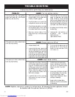
Page 17: ...IT errors are usually the result of operat ing at the highest heat setting for long periods of time room fan failure or loose wire connection Continues until the operating tempera ture falls below 90 degrees May take several minutes up to an hour Continues until the operating tempera ture falls below 90 degrees The auger will continue at the lower feed rates until the operating temperature falls b...

Page 18: ...pty refill Auger jams Remove auger and clean Auger jams can be a prob lem if poor quality fuel is used Or excessive fines sawdust corn cobs or husk are found in hopper Auger jams are evident when the auger turns but no fuel is delivered 9 9 The control board diagnostics will illuminate the A for a Vacuum Switch error and illuminate B for a Hi Limit error 9 CAUSE Auger stops turning Auger has come ...

Page 19: ...USSC 19 WIRING DIAGRAM LIMIT Downloaded from www Manualslib com manuals search engine ...

Page 20: ...AGRAM 6039 42 41 4 7 6 51 52 53 50 2 47 22 25 24 23 13 17 18 19 21 20 34 36 37 38 39 40 45 43 44 30 32 26 27 54 16 15 12 55 14 28 29 35 5 3 11 8 9 10 8 48 46 1 31 49 33 Downloaded from www Manualslib com manuals search engine ...

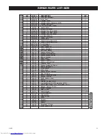
Page 21: ...Exhaust 1 26 80456 Auger Motor 1 27 83511 Washer Rubber 1 28 83533 Roll Pin 1 8 dia X 7 8 1 29 891136 Coupling Shaft 1 30 88106 Gasket Distribution Blower 1 31 80472 Blower Distribution 1 32 80486 Circuit Board 1 33 80488 Motor Drive 1 34 88111 Gasket Agitator Bracket 1 35 83534 Ring Retaining 1 36 25422 Bracket Agitator Bushing 1 37 891132 Bushing Agitator 1 38 86620 Shaft Agitator Drive 1 39 839...

Page 22: ...escritption Qty 1 25491 Feed Door 1 2 25492 Handle Door 1 3 83506 Roll Pin 3 8 x 1 1 4 1 4 88112 Gasket 1 2 Sq Rope 5 ft 5 88087 Gasket Glass 1 x 3 16 4 ft 6 891131 Glass Ceramic 1 Parts List Parts Diagrams and Parts Lists 2 1 3 4 Parts List 6039T Parts Diagram List NOTE For internal parts cabinet parts etc see pages 21 22 Key Part No Descritption Qty 1 86623 Louver 3 2 83531 Screw 10 24UNC x 2 lo...

Page 23: ...USSC 23 Notes Downloaded from www Manualslib com manuals search engine ...
Page 24: ...WHICH IS ON THE NAMEPLATE ATTACHED TO THE HEATER WHEN ORDERING REPAIR PARTS ALWAYS GIVE THE FOLLOWING INFORMATION AS SHOWN IN THIS LIST 1 THE PART NUMBER 2 THE PART DESCRIPTION 3 THE MODEL NUMBER 6039 6039T 4 THE SERIAL NUMBER ____________________ HOW TO ORDER REPAIR PARTS United States Stove Company 227 Industrial Park Road P O Box 151 South Pittsburg TN 37380 423 837 2100 WWW USSTOVE COM Downloa...

Reviews: