background image

ASSEMBLY

INSTALLATION

OPERATION

REPAIR PARTS

             CAUTION                                                    IMPROPER INSTALLATION

READ ALL INSTRUCTIONS CAREFULLY                      MAY VOID YOUR WARRANTY
BEFORE STARTING THE INSTALLATION                        SAVE THIS MANUAL FOR
       OR OPERATING THE FURNACE                                    FUTURE REFERENCE

   FOR PARALLEL INSTALLATION WITH EXISTING AIR, GAS OR OIL FIRED FURNACE

OR FOR INSTALLATION AS A CENTRAL FURNACE

DO NOT USE THIS FURNACE IN A MOBILE HOME OR TRAILER

UNITED STATES STOVE COMPANY

227 Industrial Park Rd.,  P.O.Box 151

South Pittsburg, TN 37380

(423) 837-2100

85759H  12/96

WARNOCK HERSEY

R

MODEL  1303

Owners Manual

SOLID FUEL WARM AIR FURNACE

H

TBL ST

A

O

COMPANY

U

NI

TED

STATES STO

VE

C

S

S

U

Summary of Contents for AIR

Page 1: ...UTURE REFERENCE FOR PARALLEL INSTALLATION WITH EXISTING AIR GAS OR OIL FIRED FURNACE OR FOR INSTALLATION AS A CENTRAL FURNACE DO NOT USE THIS FURNACE IN A MOBILE HOME OR TRAILER UNITED STATES STOVE COMPANY 227 Industrial Park Rd P O Box 151 South Pittsburg TN 37380 423 837 2100 85759H 12 96 WARNOCKHERSEY R MODEL 1303 Owners Manual SOLID FUEL WARM AIR FURNACE H TBL ST A O COMPANY U NITED STATES STO...

Page 2: ...t Paragraph Tools And Materials Needed TOOLS MATERIALS Pencil 6 Pipe 6 Elbow Collar and Thimble 6 Foot Folding Rule or Tape as required 24 gauge min Tin Snips 1 2 Sheet Metal Screws Drill Hand or Electric 6 Inside diameter Listed Residential Type Drill bit 1 8 dia or Building Heating Appliance Chimney For Sheet Metal Screws or existing masonry chimney See Page 8 Screw Driver Blade Type Electrical ...

Page 3: ...l or other combustible material within the marked installation clearances DO NOT store fuels paints thinners flammable liquids or other highly volatile substances in the furnace room CAUTION HOT SURFACES Keep children away Do not touch during operation SAFETY NOTICE If this heater is not properly installed a house fire may result For your safety follow the installation directions Contact local bui...

Page 4: ...a copy of the National Fire Protection Association NFPA publication Chimneys Fireplaces and Solid Fuel Burning Appliances NFPA 211 The address of the NFPA is Batterymarch Park Quincy MA 02269 11 Keep the ash pit section free of excess ashes Do not allow ashes to stack higher than the sides of the ash pan 12 DISPOSAL OF ASHES Place ashes in a metal container with a tight fitting lid Keep the closed...

Page 5: ...rnace may be installed in conjunction with a properly operat ing central furnace that is listed or certified in accordance with nationally recognized safety standards and equipped with the required con trols and other safety features and which has been installed in accordance with appropriate standards of the National Fire Protection Asso ciation with installation clearances specified in the furna...

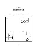
Page 6: ...1303 DIMENSIONS Shown in Fig 1 are the dimensions of the furnace 6 20 36 3 8 32 1 8 2 30 9 16 41 Fig 1 ...

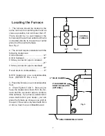
Page 7: ... connector pipe to backwall 18 Hot air ducts to combustibles 6 NOTE Install only on a noncombustible floor REFER TO FIG 2 3 3 Place the furnace on a noncombustible floor 4 Check figures 2 and 3 Be sure you have the clearances shown from the fur nace and the connector pipe to combus tible surfaces If you have a solid brick or stone wall behind your heater you can place the furnace as close as you w...

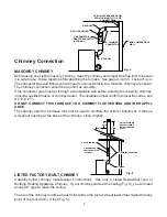
Page 8: ... for a furnace must not be used to ventilate the cellar or basement If there is a cleanout opening at the base of the chimney close it tightly LISTED FACTORY BUILT CHIMNEY Carefully follow chimney manufacturer s instructions Use only a Listed Residential Type or Building Heating Appliance Chimney If your chimney starts at the ceiling Fig 5 you will need enough 6 pipe to reach the ceiling The top o...

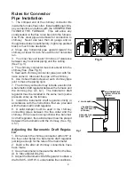
Page 9: ...tion for a barometric draft regulator between the furnace and the chimney fig 4 5 7 The barometric draft regulator must be installed in the same room same pressure zone as the furnace 8 Install the barometric draft regulator strictly in accordance with the instructions that are provided with the barometric draft regulator 9 A solid damper must be used in the chimney connecting pipes between the fl...

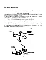
Page 10: ...ywell Fan Limit Control on rear of cabinet as shown in Fig 8 NOTE Remove cover of Fan Limit control for access to screw holes 4 Remove blower from carton and inspect for damage Remove cover from 4 junction box on rear of furnace See Fig 8 5 Attach clip nuts to blower opening on rear of furnace as shown Install blower and gasket using 1 4 20x3 4 bolts provided 6 Complete all wiring in 4 junction bo...

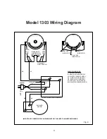
Page 11: ... Honeywell LIMIT SWITCH R1 R2 G W 110 VAC 60 HZ GROUND G B W ELECTRICAL JUNCTION BOX M1 M2 BLOWER MOTOR IMPORTANT POWER SUPPLY WIRING MUST NOT BE LESS THAN 90 CENTIGRADE POWER CORD WIRE COLOR CODE G GREEN GROUND B BLACK POWER SUPPLY W WHITE POWER SUPPLY R1 WHITE FAN CONTROL R2 BLACK FAN CONTROL M1 BLACK FAN CONTROL M2 WHITE BLOWER MOTOR Fig 9 ...

Page 12: ...lation must be made only on a noncom bustible floor d Install the smoke pipe connector to the chim ney with 26 gauge pipe and elbows to be pur chased separately maintaining the proper clear ances for the specific model Seal the spoke pipe in the chimney with furnace cement The chimney connector shall be securely supported and joints fastened with sheet metal screws or rivets e Install 8 diameter h...

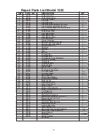
Page 13: ...43 Thermostat 1 27 89142 Thermostat Knob 1 28 23463 Cabinet Bottom 1 29 23303 Access Plate 1 30 89354 Door Handle Feed Door 1 31 89354 Door Handle Ash Door 1 32 88033 3 8 Rope Gasket 44 33 88033 3 8 Rope Gasket 29 35 68561 Base Assembly 1 36 88064 Air Box Cover Gasket 1 37 68587 Outlet Baffle Weldment 1 38 23193 Baffle Bracket 1 39 22247 Front Firebox Liner 1 40 66080 Grate Liner Support 2 41 2209...

Page 14: ...14 MODEL 1303 See Repair Parts List on Page 13 9 10 41 11 38 7 6 3 1 2 39 4 25 23 24 22 20 17 14 18 16 13 15 26 37 34 35 33 32 31 36 29 28 27 40 19 5 8 30 12 21 42 ...

Page 15: ...ons Operation after loss of power 1 Remove filter if provided 2 Do not expect to keep home at normal temperatures 3 Do not load fuel above bottom of feed door 15 2 MIN AIR SPACE REQUIRED BY CODE 18 MIN CENTRAL FURNACE Fig 10 ...

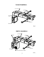
Page 16: ...6 PIPE DAMPER OPTIONAL 11 RPT 90 ELBOW FURNACE PIPE CONNECTOR Central Installation Fig 11 Add On Installation COLD AIR DUCT 6 PIPE DAMPER 90 ELBOW FURNACE PIPE CONNECTOR EXISTING GAS OIL ELECTRIC FURNACE 8 PIPE FIG 11 B ...

Page 17: ...ed door and place paper and kindling on the grate for starting the fire 3 Light fire and close feed door 4 Add wood after fire is burning briskly Be careful not to smother the kindling fire 5 Set thermostat for desired temperature MEDIUM setting is normally satisfactory Set higher or lower for your comfort ADDING FUEL When starting a fire use small amounts of fuel This will allow for more complete...

Page 18: ...point of the roof within 10 feet Fig 5 See page 19 for list of trouble shooting tips 5 6 A draft reading of 05 to 06 w c is suggested for proper burning of this unit when using wood Chimney Maintenance Creosote and Soot Formation and Need for Removal When wood is burned slowly it produces tar and other organic vapors which combine with expelled moisture to form creosote The creo sote vapors conden...

Page 19: ... from furnace and duct work a Burning green wood not seasoned or dry b Thermostat setting too low for type fuel a Insufficient draft b Smothering fire when adding fresh fuel a Set thermostat higher b Clean chimney c Add raincap to chimney a Allow wood to season in a dry well ventilated area for 6 mo b Set blower control to higher temperatures c Set flue draft See page 9 a Wire unit properly b Repl...

Page 20: ...20 COLD AIR RETURN TO EXISTING DUCT WORK WARM AIR EXISTING FURNACE MODEL 1303 FURNACE FILTER BOX APPENDIX INSTALLATION A ...

Page 21: ...D AIR RETURN TO EXISTING DUCT WORK WARM AIR EXISTING FURNACE MODEL 1303 FURNACE FILTER BOX PLENUM COLLECTOR BOX COLD AIR RETURN TO EXISTING DUCT WORK WARM AIR EXISTING FURNACE MODEL 1303 FURNACE FILTER BOX PLENUM ELBOW PLENUM TOP OPTIONAL ...

Page 22: ...PLENUM FAN CONTROL LOCATION FURNACE PLENUM EXISTING FURNACE ANTI BACKDRAFT FLAPPER SOLID FUEL FURNACE COLD AIR RETURN INSTALLATION D 2 MINIMUM CLEARANCE DUCT WORK FURNACE PLENUM EXISTING FURNACE SOLID FUEL FURNACE COLD AIR RETURN INSTALLATION E BAFFLE ...

Page 23: ...ANCE DUCT WORK FURNACE PLENUM EXISTING FURNACE SOLID FUEL FURNACE COLD AIR RETURN INSTALLATION F 2 MINIMUM CLEARANCE DUCT WORK SOLID FUEL FURNACE INSTALLATION G COLD AIR RETURN TO FILTER BOX CENTRAL FURNACE INSTALLATION ...

Page 24: ...S ON THE NAMEPLATE ATTACHED TO THE FRONT OF THE FURNACE WHEN ORDERING REPAIR PARTS OR OPTIONS ALWAYS GIVE THE FOLLOWING INFORMATION AS SHOWN IN THIS LIST 1 The PART NUMBER 2 The PART DESCRIPTION 3 The MODEL NUMBER 1303 4 The SERIAL NUMBER BEFORE INSTALLING YOUR HEATER FILL IN THE SERIAL NUMBER IN THE SPACE PROVIDED ABOVE FOR YOUR RECORDS UNITED STATES STOVE COMPANY 227 Industrial Park Rd P O Box 1...

Reviews: