background image

11

Crimped end of the pipe must be installed toward the heater. The
pipe should slide inside the flue collar. The pipe should be firmly
attached to the flue collar with 3 screws and sealed with furnace
cement.
Slope any horizontal pipe upward toward the chimney at least 1/4
" inch for each foot of horizontal run.
You must have at least 18" inches clearance between any horizon-
tal piping and the ceiling.
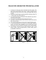
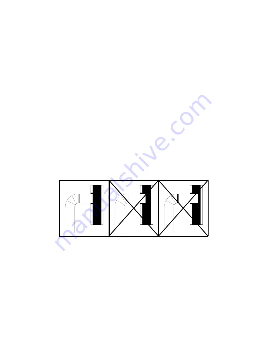
The pipe cannot extend into the chimney flue.(Fig. 8)
Seal each connector pipe joint with furnace cement. Also seal the
pipe at the chimney.
Use 3 sheet metal screws at each joint to make the piping rigid.
It is recommended that no more than two (2) 90 degree bends be
used in the stove pipe installation as more than two (2) may
decrease the amount of draw and possibly cause smoke spillage.
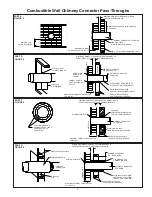
The chimney connector must not pass through an attic or roof
space, closet, or any concealed space, or floor, ceiling, wall or
combustible construction.

1.

2.

3.

4.
5.

6.
7.

8.

RULES FOR CONNECTOR PIPE INSTALLATION

Fig. 11

Summary of Contents for APS1100B

Page 1: ...onsmayresult inpropertydamage bodilyinjury or even death Improper installation could void your warranty TESTED TO UL1482 COMPANY UNITEDSTATESSTOVE C S S U COMPANY UNITEDSTATESSTOVE C S S U SAVE THIS MANUAL FOR FUTURE REFERENCE THIS MANUAL WILL HELP YOU TO OBTAIN EFFICIENT DEPENDABLE SERVICE FROM THE HEATER AND ENABLE YOU TO ORDER REPAIR PARTS CORRECTLY KEEP IN A SAFE PLACE FOR FUTURE REFERENCE Pt ...

Page 2: ...rer of wood burning products By heating with wood you re helping to CONSERVE ENERGY Wood is our only Renewable Energy Resource Please do your part to preserve our wood supply Plant at least one tree each year Future generations will thank you Dimensions SIDE VIEW FRONT VIEW TOP VIEW ...

Page 3: ... USE To prevent injury do not allow anyone to use this heater who is unfamiliar with the correct operation of the heater For additional information on using your Room Heater safely obtain a copy of the National Fire Protection Association NFPA publication Chimneys Fireplaces and Solid Fuel Burning Appliances NFPA No 211 USA 1 2 3 4 5 6 7 8 9 10 11 12 13 14 15 16 17 18 19 20 21 22 23 Disposal of As...

Page 4: ...e below 3 Check figures below You should have at least the clearances shown from the heater and the connector pipe to combustible surfaces If you have a solid brick or stone wall behind your heater you can place the heaterascloseasyouwishtothewall Ifthewallisonly faced with brick or stone treat it as a combustible wall LOCATING THE ROOM HEATER AS A LOCATION IS SELECTED KEEP THE FOLLOWING IN MIND M...

Page 5: ...TY 1 Blower Motor 80442 1 2 Blower Housing Front 25090B 1 3 Blower Housing Back 25089B 1 4 Power Supply Cord 80232 1 5 Rheostat w Nut and Knob 80090 1 6 Strain Relief Bushing 80109 1 N S 10AB x 3 8 Hex Zinc Screw 83222 8 N S 12 x 3 4 Teks Screw C23799 4 ASSEMBLY INSTRUCTIONS Step 1 THE BLOWER ASSEMBLY MUST BE DISCON NECTEDFROMTHESOURCEOFELECTRICALSUP PLYBEFOREATTEMPTINGTHEINSTALLATION With pliers ...

Page 6: ...ffing smoke spillage and to maximize performance Chimneysperformtwofunctions oneofwhich is apparent The chimney provides a means forexhaustingsmokeandfluegasesresulting from combustion of the fuel Secondarily though the chimney provides Draft which allows oxygen to be continuously introduced into the appliance so that proper combustion is possible As of April 1 1987 all wood heatersandfurnacesmanu...

Page 7: ...RS PARTS TO ATTACH CONNECTOR SECURELY AIR SPACE TWO VENTILATED AIR CHANNELS EACH 1 INCH CONSTRUCTED OF SHEET STEEL PART C FIGURE 9 MASONRY CHIMNEY CONSTRUCTED TO NFPA 211 SHEET STEEL SUPPORTS 24 GAUGE MIN THICKNESS MINIMUM CHIMNEY CLEARANCES FROM MASONRY TO SHEET STEEL SUPPORTS AND COMBUSTIBLES 2 IN MINIMUM 6 IN GLASS FIBER INSULATION ALL AROUND 24 GAUGE VENTILATED THIMBLE WITH TWO 1 INCH AIR CHAN...

Page 8: ...which are at least 24 gauge 0 024 in thickness The sheet steel supports shall be securely fastened to wall surfaces on all sides and shall be sized to fit and hold the chimney section Fasteners used to secure chimney sections shall not penetrate chimney flue liner Method D 2 Clearance to Combustible Wall Member Use an 8 inside diameter solid insulated listed factory built chimney length which has ...

Page 9: ...ome people is to vent the heater directly into the fireplace This does not meet code since the heater is being vented into another appliance the fireplace This method should not be attempted because combustion products will deposit and build up in the firebox or fireplace Be certain not to install a hazard in your house You will void your warranty with this installation VENTING INTO A MASONRY CHIM...

Page 10: ...t the thimble is flush with the inner flue lining secure the thimble in place with refractory mortar The thimble should be surrounded on all sides with8inchesofbrickwork solidmasonryunits or 24 inches of stone Install the stovepipe as far as possible into the thimble but not past the inside of the flue lining There should be a small airspace approximately 1 2 inch between the stovepipe and thimble...

Page 11: ...iling The pipe cannot extend into the chimney flue Fig 8 Seal each connector pipe joint with furnace cement Also seal the pipe at the chimney Use 3 sheet metal screws at each joint to make the piping rigid It is recommended that no more than two 2 90 degree bends be used in the stove pipe installation as more than two 2 may decrease the amount of draw and possibly cause smoke spillage The chimney ...

Page 12: ...for a heater must not be used to ventilate the cellar or basement If there is a cleanout opening at the base of the chimney It must be closed tightly 1 2 3 4 5 If the chimney is operating too cool water will condense in the chimney and run back into the stove Creosote formation will be rapid and may block the chimney Operate the heater at a high enough fire to keep the chimney warm preventing this...

Page 13: ...ch Spacer AF0034 1 12 Door Latch AF0007 1 13 Door Latch Bushing AF0035 1 14 10 24 x 3 8 PH Bolt 83202 4 15 Bottom Bracket AF0024 1 16 Door Glass AF0038 1 17 Glass Gasket 88087 1 18 Door Gasket 88066 1 19 Feed Door AF0036 1 20 Door Handle AF0020 1 21 Brass Handle 89574 1 22 Top Bracket AF0025 1 23 Door Hinge Pin AF0023 2 24 Firebrick 4 5 x 9 x 1 25 89066 12 25 Firebrick 4 5 x 7 38 x 1 25 AF0021 4 2...

Page 14: ...MBLY WARNING DO NOT ROUTE THE SUPPLY CORD NEAR OR ACROSS HOT SURFACES CAUTION THE BLOWER ASSEMBLY MUST BE DISCON NECTED FROM THE SOURCE OF ELECTRICAL SUPPLY BEFORE AT TEMPTING ANY MAINTE NANCE BRICK PLACEMENT TOP INSIDE VIEW OF FIREBOX ...

Page 15: ...should never be placed in a wooden cardboard or plastic container nor in a paper or plastic bag no matter how long the fire has been out Coals have been known to stay hot for several days when embedded in ashes Glass Replacement Instructions for APS1100B 7 8 9 10 11 Use only the glass specified for this unit Contact your local dealer or customer ser vice for replacement glass Warning Do not slam d...

Page 16: ...LWAYS GIVE THE FULL MODEL NUMBER WHICH IS ON THE NAME PLATE ATTACHED TO THE BACK OF THE HEATER WHEN ORDERING REPAIR PARTS ALWAYS GIVE THE FOLLOWING INFORMATION AS SHOWN IN THIS LIST UNITED STATES STOVE COMPANY 227 Industrial Park Road P O Box 151 South Pittsburg TN 37380 1 800 750 2723 www USSTOVE com 1 The PART NUMBER 2 The PART DESCRIPTION 3 The MODEL NUMBER APS1100B 4 The SERIAL NUMBER ________...

Reviews: