5
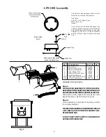
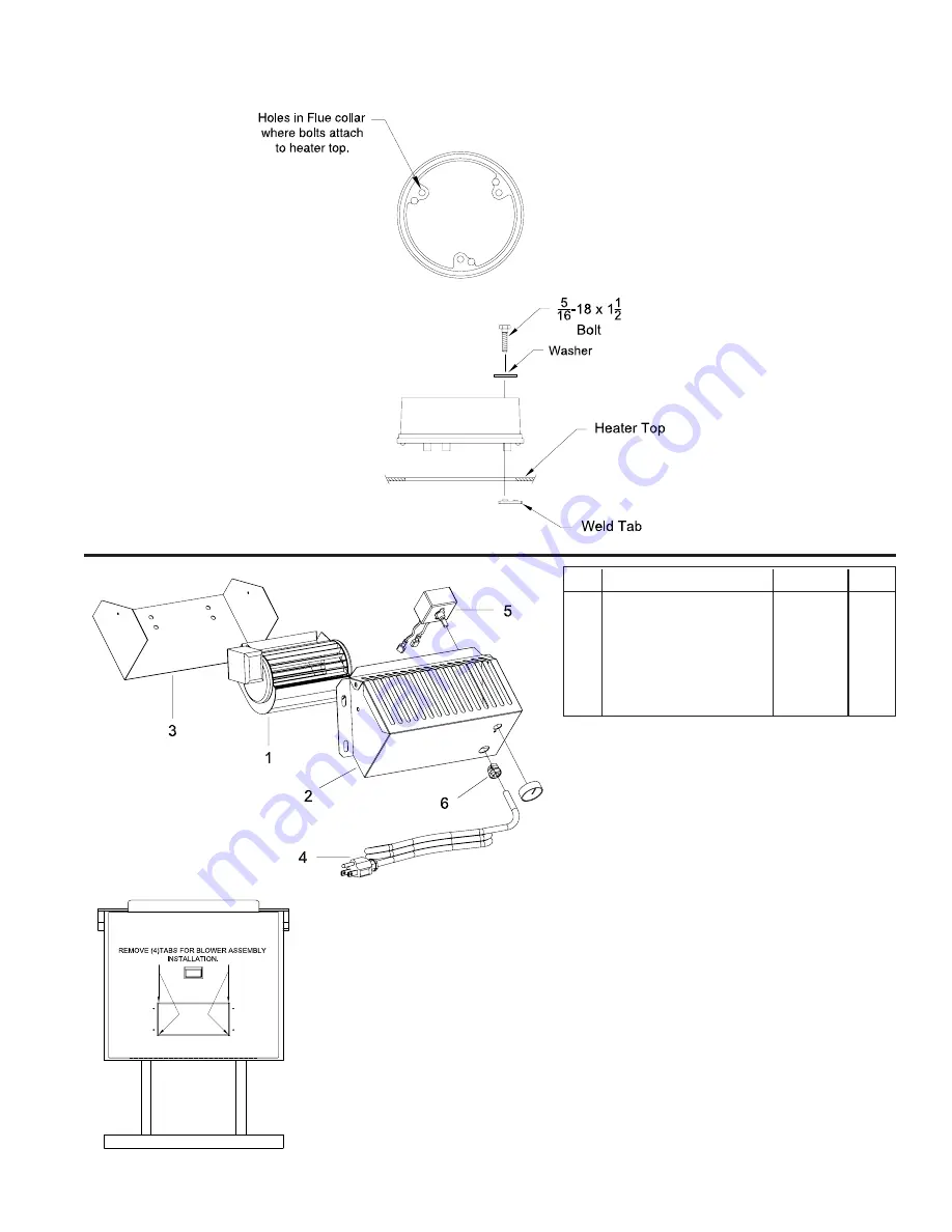
This heater comes equipped with a cast-iron
flue collar to mount as shown below:
Flue Collar
5/16-18 x 1-1/2" Bolts (3 req.)
Weld Tab (3 req.)
Gasket
Peel off tape from the back of the gasket and
attach the gasket to the rope groove in the flue
collar. Mount flue collar to the top of the heater
using the (3) 5/16-18 x 1-1/2" Bolts, Washers,
and the (3) Weld tabs provided in the parts
bag.
APS1100 Assembly
Side view of flue collar
mount to heater top
Flue Collar
Fig. 5
(Stove Back)
Fig. 6
KEY DESCRIPTION
PART NO. QTY.
1
Blower Motor
80442
1
2
Blower Housing Front
25090B
1
3
Blower Housing Back
25089B
1
4
Power Supply Cord
80232
1
5
Rheostat w/Nut and Knob
80090
1
6
Strain Relief Bushing
80109
1
N/S
10AB x 3/8 Hex Zinc Screw
83222
8
N/S
#12 x 3/4 Teks Screw
C23799
4
ASSEMBLY INSTRUCTIONS
Step 1.
THE BLOWER ASSEMBLY MUST BE DISCON-
NECTED FROM THE SOURCE OF ELECTRICAL SUP-
PLY BEFORE ATTEMPTING THE INSTALLATION.
With pliers, cut the 4 tabs and remove panel on the
back of the stove. Note: Discard the panel.
Step 2.
Fix the assembly to the back of the stove with the
four screws provided.
THE BLOWER ASSEMBLY IS INTENDED FOR USE
ONLY WITH A STOVE THAT IS MARKED TO IN-
DICATE SUCH USE.
DO NOT ROUTE THE SUPPLY CORD NEAR OR
ACROSS HOT SURFACES!

