11
USSC
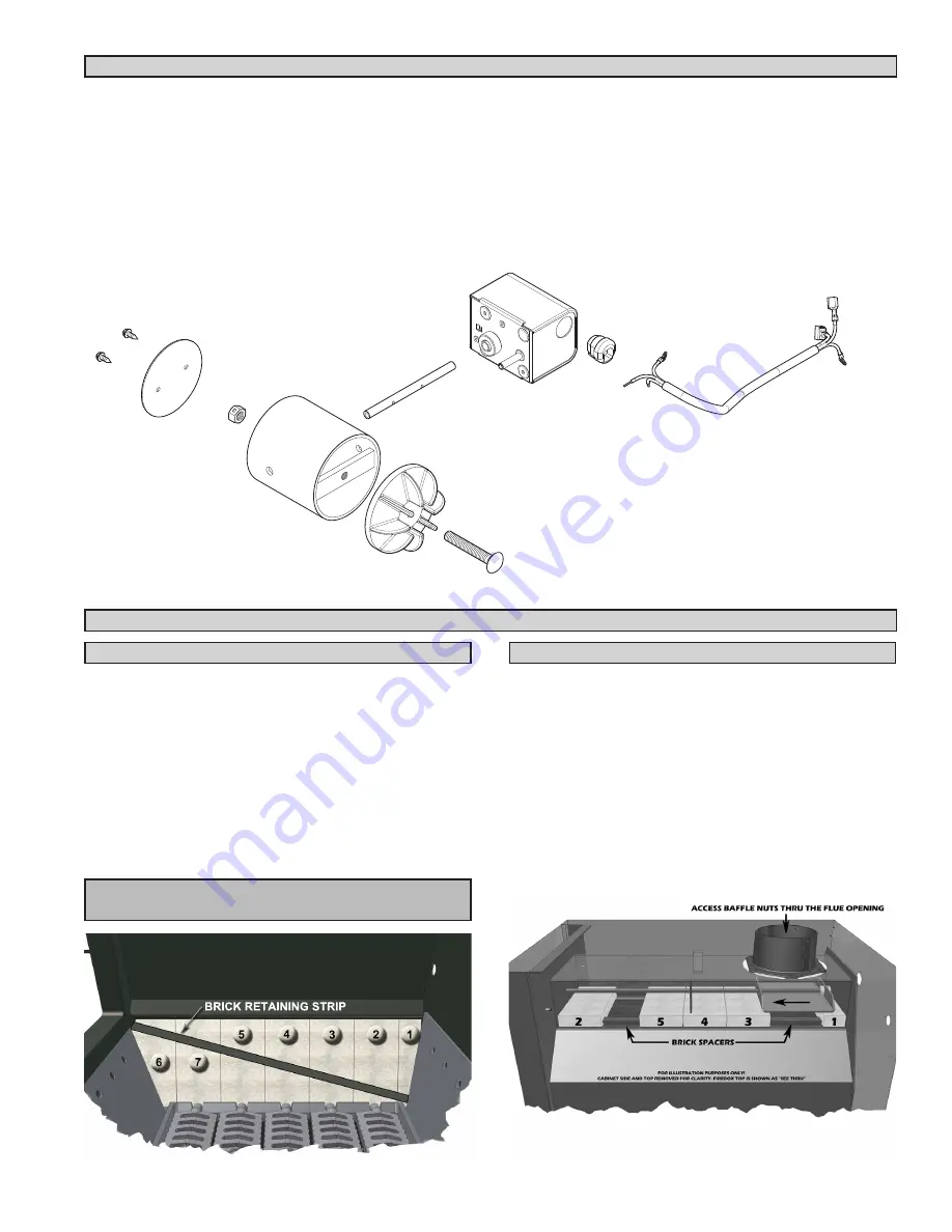
This furnace comes from the factory with the firebrick in-
stalled. However, if brick replacement is necessary, follow
these instructions. Before furnace operation, remove the
brick retaining strip. This piece is used during shipping to
reduce brick damage.
There are
6 full brick and 1 half brick per side
. Install the
half brick first by putting the bottom of the brick in first and
let it rest against the firebox side and fire grates. Then slide
it to the rear. After that, install the #2, #3, #4, #5 & #6 brick,
sliding the 6th brick forward to allow for the 7th brick. Re-
peat for opposite side.
NOTE: Prior to operation, be sure to remove the brick
retaining strips.
1.
Make certain the unit has been unplugged from the
power source.
Remove the cover from the motor and
remove the two wire nuts and grounding screw. With a
pair of pliers, remove the strain relief and cord assem-
bly from the motor.
If motor comes with the cord, the above step is not
required. However, you will have to remove the panel
on the inner cabinet side to rewire the motor. Do so by
removing the rivets with a 3/16” drill bit. Screws may be
used to replace the rivets.
If baffle replacement is necessary
, slide the baffle out until
you can access the nuts thru the flue outlet. Once the
nuts have been removed, slide the baffle off the rod and
thru the opening in the firebrick. You may have to remove
one of the firebrick to make baffle removal easier.
There are
4 full brick and 1 half brick in the top of the fur-
nace
. Install the brick by inserting one end of the brick an-
gled upward and then allowing the opposite end to rest
on the firebox lip. Lay the brick between the spacer and
firebox back. Slide the baffle to the rear and let it rest on
that half brick. After installing brick #2 in the front, install #3
and slide it under the baffle. Finally install bricks #4 and #5.
MOTORIZED NATURAL DRAFT REPLACEMENT
FIREBRICK AND BAFFLE REPLACEMENT
BAFFLE/BRICK REPLACEMENT
FIREBOX BRICK REPLACEMENT
2. Remove the draft assembly from the furnace by loos-
ening the two bolts retaining draw band.
3. To remove the motor from the tubing assembly, simply
loosen the set screw in the collar on the motor and slide
it off the tube.
4. If replacing the Flipper, remove the two #8 screws re-
taining the plate to the tube.
Reverse the above steps for re-assembly
(1) Draft Actuator
(1) Spin Draft
(1) 3/8-16 Carriage Bolt
(1) 3/8-16 Lock Nut
(1) Flipper Tube
(1) Flipper
(2) #8 Screw
Summary of Contents for Clayton 1600EF
Page 15: ...15 USSC WIRING DIAGRAM ...
Page 16: ...16 USSC PARTS DIAGRAM ...
Page 20: ...20 USSC NOTES ...


