4
■
RF Touch Panel Network Configuration
■
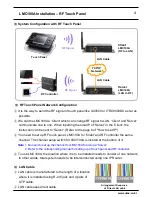
LAN Cable
Arrangement Sequence
of Direct LAN cable
①
LAN cable is manufactured to the length of a location
where it is installed using RJ-45 jack and 4 pairs of
UTP cable.
②
LAN cable uses direct cable.
①
It is the way to send the RF signal of touch panel like UX3500 or ITRC8500DX as far as
possible.
②
We call the LMC100A a 'Client' which can change RF signal to LAN. 'Client' and 'Server'
communicate one to one. When inputting the local IP of 'Server' in the 'Client', the
instruction can be sent to 'Server'. (Refer to the page 8 of "How to set IP")
③
You need to set up RF touch panel, LMC100A for 'Client' and RF controller the same
channel. The channel setup switch for LMC100A is located at the bottom of it.
Note
1. No need to set up the channel for LMC100A for using a 'Server'.
2. Refer to the corresponding manual for setting up of touch panel and RF controller.
④
To use LMC100A, the location where it is to be installed needs to consist of one network.
In other words, total system needs to be interconnected using one IP Router.
Touch Panel
RF Signal
Client
LMC100A
(RF to LAN)
Server
LMC100A
(LAN to RF)
RF Signal
LAN Cable
LAN Cable
RF Controller
TCP/IP
Network
www.utas.co.kr
■
System Configuration with RF Touch Panel
LMC100A Installation
– RF Touch Panel


