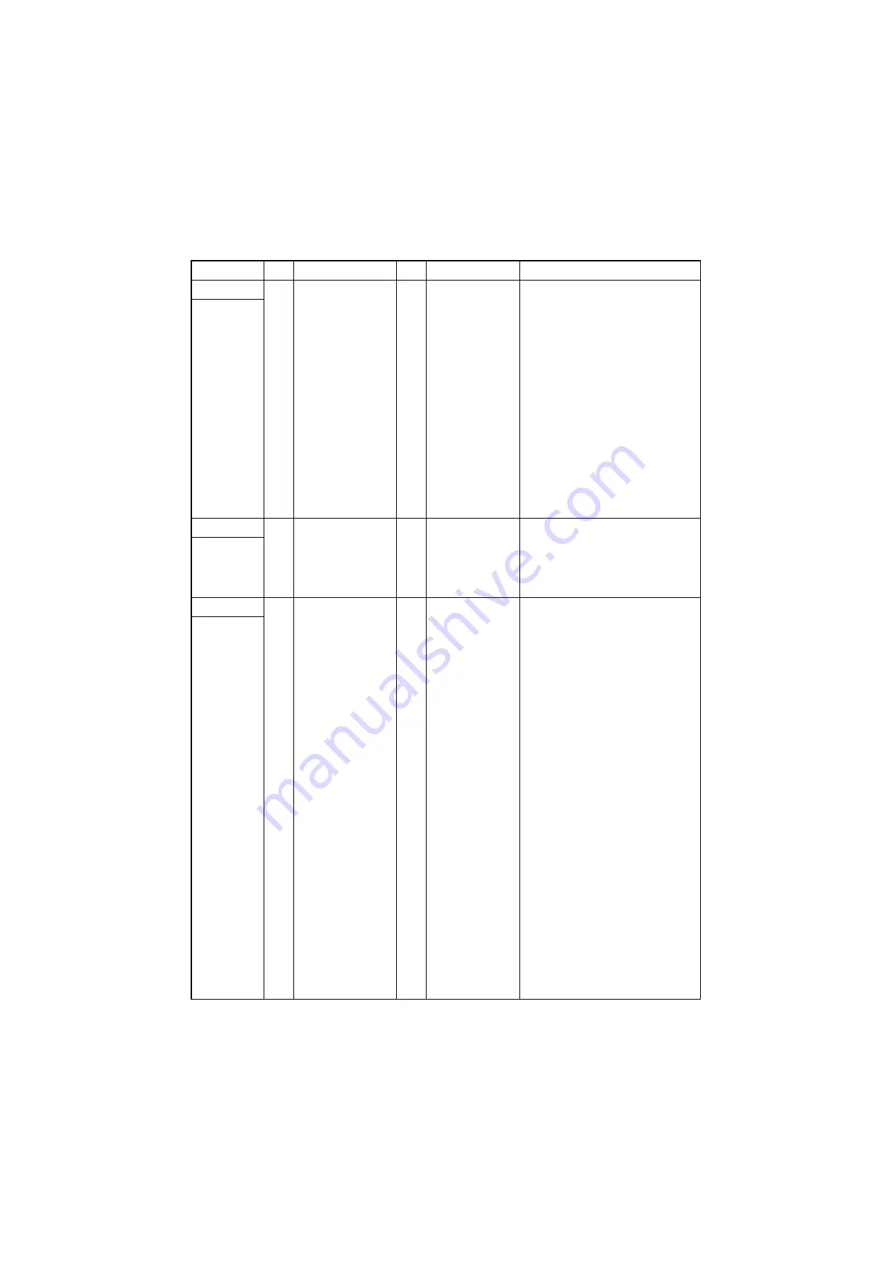
3N0/3NK/3PD/3PG
2-3-11
YC3
1
GND
-
-
Ground
Connected to
the DF main
PWB
2
GND
-
-
Ground
3
GND
-
-
Ground
4
5V
I
5 V DC
5 V DC power input
5
24V
I
24 V DC
24 V DC power input
6
24V
I
24 V DC
24 V DC power input
7
SDI
I
0/5 V DC (pulse)
Mailbox serial communication data
signal
8
SDO
O
0/5 V DC (pulse)
Mailbox serial communication data
signal
9
SCLK
I
0/5 V DC (pulse)
Mailbox clock signal
10
SEL
I
0/5 V DC
Mailbox select signal
11
READY
O
0/5 V DC
Mailbox ready signal
YC4
1
R24V
I
24 V DC
24 V DC power input
Connected to
the mailbox
cover open/
close switch
3
24V
O
24 V DC
24 V DC power output
YC5
1
MOTOR _A
O
0/24 V DC (pulse) MBDM drive control signal
Connected to
the mailbox
drive motor
2
MOTOR A
O
0/24 V DC (pulse) MBDM drive control signal
3
MOTOR B
O
0/24 V DC (pulse) MBDM drive control signal
4
MOTOR _B
O
0/24 V DC (pulse) MBDM drive control signal
Connector
Pin
Signal
I/O
Voltage
DescrIption
Summary of Contents for AK 740
Page 1: ...Service Manual RFXPHQW LQLVKHU D 07 3 LUVW GLWLRQ Date 2 0 20 3 SM06 ...
Page 2: ...Service Manual RFXPHQW LQLVKHU D 07 3 LUVW GLWLRQ Date 2 0 20 3 SM06 ...
Page 4: ...Revision history Revision Date Pages Revised contents ...
Page 5: ...This page is intentionally left blank ...
Page 11: ...This page is intentionally left blank ...
Page 17: ...3N0 3NK 3PD 3PG 1 1 4 2 Mail box option Figure 1 1 2 1 2 1 Trays 1 7 2 Mailbox cover ...
Page 29: ...3N0 3NK 3PD 3PG 1 2 10 This page is intentionally left blank ...
Page 45: ...3N0 3NK 3PD 3PG 1 3 16 This page is intentionally left blank ...
Page 129: ...3N0 3NK 3PD 3PG 2 2 9 This page is intentionally left blank ...
Page 155: ...1 1 INSTALLATION GUIDE DF 791 3000 sheet finisher Installation Guide ...
Page 170: ...AK 740 Bridge unit Installation Guide ...
Page 172: ...MT 730 B Mail box Installation Guide ...


