1-3-23
2GM
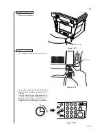
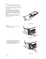
3. Connect the modular cord to the line jack.
120 V specifications: Connect the modular cord
with the attached ferrite core to the machine.
Line jack
Figure 1-3-51
20 mm
Ferrite
core
Figure 1-3-52
220-240 V specifications only
4. Attach the core to the power cord of the machine
so that the stopper section is located near the
power plug as shown in the illustration.
Figure 1-3-53
5. Plug the power cord into the machine. Turn the
machine on.
NOTE (120 V specifications only)
When connecting a separate phone to the
machine, attach the ferrite core to the modular
cord before connection. Loop the modular cord
through the ferrite core.
Core
Stopper section
Summary of Contents for CD 1018
Page 1: ...Service Manual MFP Copy CD 1018 Date 17 03 2005 ...
Page 2: ...Service Manual MFP Copy DC 2018 Date 17 03 2005 ...
Page 70: ...2GM 1 5 2 2 Paper misfeed detection conditions Registration sensor Exit sensor Figure 1 5 2 ...
Page 124: ...2GM 1 6 31 Eraser lamp 9 Remove the eraser lamp Figure 1 6 35 Removing the eraser lamp ...

