2DA/2DB
1-5-18
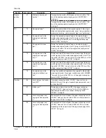
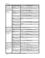
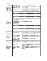
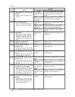
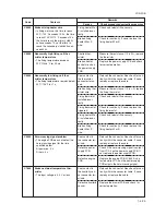
(2) Self diagnostic codes
Code
Contents
Remarks
Causes
Check procedures/corrective measures
C0030
C0070
C0100
C0110
C0130
C0140
C0150
C0160
C0170
C0180
Fax control PCB
*
1
system problem
• Processing with the fax software was
disabled due to a hardware or soft-
ware problem.
Fax control PCB
*
1
incompatibility
detection problem
• Fax software is not compatible with
MMI software.
Backup memory read/write problem
(main PCB flash)
• Read and write data does not match.
Backup memory data problem (main
PCB flash)
• Data in the specified area of the
backup memory does not match the
specified values.
Backup memory read/write problem
(main PCB EEPROM)
• Read and write data does not match.
Backup memory data problem (main
PCB EEPROM)
• Data in the specified area of the
backup memory does not match the
specified values.
Backup memory read/write problem
(engine PCB)
• Read and write data does not match.
Backup memory data problem (en-
gine PCB)
• Data in the specified area of the
backup memory does not match the
specified values.
Accounting count problem
• When the power is turned on, the to-
tal count and the scan count are ab-
normal both on the main PCB and the
engine PCB.
Machine number mismatch
• When the power is turned on, the ma-
chine number does not match be-
tween the main PCB and the engine
PCB.
Defective fax con-
trol PCB.
Fax software or
main software is
something of the
other machine.
Defectivemain
PCB.
Problem with the
backup memory
data.
Defective backup
RAM.
Defective
EEPROM or main
PCB.
Problem with the
backup memory
data.
Defective
EEPROM.
Defective engine
PCB.
Problem with the
backup memory
data.
Defective backup
RAM.
Defective main
PCB or engine
PCB.
Correct EEPROM
is not installed.
Data damage of
EEPROM.
Replace the fax control PCB and check for
correct operation.
Check the version of the Fax software and
the main software, upgrade the version to
the compatible software.
Replace the main PCB and check for cor-
rect operation.
Turn safety switch off and back on and run
maintenance item U020 to set the contents
of the backup memory data again.
If the C0110 is displayed after re-setting
the backup memory contents, replace the
main PCB.
Replace the main PCB and check for cor-
rect operation.
Turn safety switch off and back on and run
maintenance item U020 to set the contents
of the backup memory data again.
If the C0140 is displayed after re-setting
the backup memory contents, replace the
EEPROM or main PCB.
Replace the engine PCB and check for
correct operation.
Turn safety switch off and back on and run
maintenance item U020 to set the contents
of the backup memory data again.
If the C0160 is displayed after re-setting
the backup memory contents, replace the
engine PCB.
Replace the main PCB or engine PCB and
check for correct operation.
Install the correct EEPROM. If it does not
solve the problem, contact the Service Ad-
ministrative Division.
Contact the Service Administrative Divi-
sion.
*1: Optional. *2: Optional for 16 ppm model. Standard for 20 ppm model.
Summary of Contents for cd 1116
Page 1: ...Service Manual Copy CD 1116 CD 1120 Rev 1 ...
Page 2: ...Service Manual Copy DC 2116 DC 2120 Rev 1 ...
Page 4: ...This page is intentionally left blank ...
Page 247: ...2DA 2DB 1 2 3 2 Figure 2 3 2 Power source PCB silk screen diagram 220 240 V AC 120 V AC ...
Page 264: ...2DA 2DB 1 2 3 19 Figure 2 3 10 Operation unit PCB silk screen diagram ...


