2DA/2DB
1-5-20
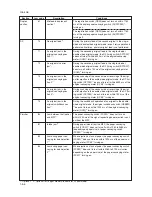
Code
Contents
Remarks
Causes
Check procedures/corrective measures
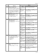
C0510
C0610
C0630
C0800
C0820
C0830
C0860
C0870
C0880
Third paper feeder
*
1
communication
problem
• Communication fails five times suc-
cessively.
Bitmap (DIMM) problem
• There is a problem with the data or
address bus of the bitmap DRAM.
DMA problem
• DMA transmission of compressed,
decompressed, rotated, relocated or
blanked-out image data does not
complete within the specified period
of time.
Image processing problem
• JAM05 is detected twice.
Fax control PCB
*
1
CG ROM
checksum error
• A checksum error occurred with the
CG ROM data of the fax control PCB.
Flash ROM program area checksum
error
• A checksum error occurred with the
program of the fax control PCB.
Fax control PCB
*
1
software switch
checksum error
• A checksum error occurred with the
software switch value of the fax con-
trol PCB.
Fax control PCB
*
1
to main PCB high-
capacity data transfer problem
• High-capacity data transfer between
the fax control PCB and the main
PCB of the machine was not normally
performed even if the data transfer
was retried the specified times.
Fax control PCB
*
1
program archive
problem
• When power is turned on, the com-
pressed program in the Flash ROM
on the fax control PCB was not suc-
cessfully decompressed.
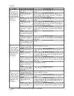
Paper feeder in-
stalled incorrectly.
Defective engine
PCB or drawer
main PCB.
Defective main
PCB.
DIMM installed
incorrectly.
Defective DIMM.
Defective main
PCB.
Defective main
PCB.
Defective fax con-
trol PCB.
Defective fax con-
trol PCB.
Defective fax soft-
ware.
Defective fax con-
trol PCB.
Poor contact in
the connector ter-
minals.
Defective main
PCB or fax control
PCB.
Defective fax con-
trol PCB.
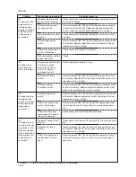
Check the installation state of the paper
feeder and adjust it if it is not properly in-
stalled.
Replace the engine PCB or drawer main
PCB and check for correct operation.
Replace the main PCB and check for cor-
rect operation.
Check if the DIMM is inserted into the
socket on the main PCB correctly.
Replace the DIMM and check for correct
operation.
Replace the main PCB and check for cor-
rect operation.
Replace the main PCB and check for cor-
rect operation.
Replace the fax control PCB and check for
correct operation.
Replace the fax control PCB and check for
correct operation.
Install the fax software to Ver. 2.xx or later.
Replace the fax control PCB and check for
correct operation.
Check the connection of connector. Repair
or replace if necessary.
Replace the main PCB or fax control PCB
and check for correct operation.
Replace the fax control PCB and check for
correct operation.
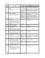
*1: Optional. *2: Optional for 16 ppm model. Standard for 20 ppm model.
Summary of Contents for cd 1116
Page 1: ...Service Manual Copy CD 1116 CD 1120 Rev 1 ...
Page 2: ...Service Manual Copy DC 2116 DC 2120 Rev 1 ...
Page 4: ...This page is intentionally left blank ...
Page 247: ...2DA 2DB 1 2 3 2 Figure 2 3 2 Power source PCB silk screen diagram 220 240 V AC 120 V AC ...
Page 264: ...2DA 2DB 1 2 3 19 Figure 2 3 10 Operation unit PCB silk screen diagram ...

