2DA/2DB
1-5-27
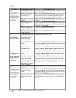
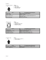
(1) No image appears
(entirely white).
Causes
1. No transfer charging.
2. No LSU laser is output.
3. No developing bias is output.
Causes
Check procedures/corrective measures
1. No transfer charging.
A. The connector terminals of the high-voltage
PCB make poor contact.
B. Defective engine PCB.
C. Defective high-voltage PCB.
2. No LSU laser is output.
A. Defective laser scanner unit.
B. Defective main PCB.
3. No developing bias is output.
A. The connector terminals of the high-voltage
PCB make poor contact.
B. Defective engine PCB.
C. Defective high-voltage PCB.
Reinsert the connector. Also check for continuity within the
connector cable. If none, remedy or replace the cable.
Replace the engine PCB and check for correct operation.
Replace the high voltage PCB and check for correct operation.
Replace the laser scanner unit (see page 1-6-29).
Replace the main PCB and check for correct operation.
Reinsert the connector. Also check for continuity within the
connector cable. If none, remedy or replace the cable.
Replace the engine PCB and check for correct operation.
Replace the high voltage PCB and check for correct operation.
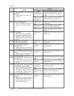
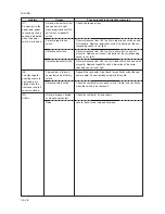
(2) No image appears
(entirely black).
Causes
1. No main charging.
2. Exposure lamp fails to light.
Causes
Check procedures/corrective measures
1. No main charging.
A. Broken main charger wire.
B. Leaking main charger housing.
C. The connector terminals of the high-voltage
PCB make poor contact.
D. Defective engine PCB.
E. Defective high-voltage PCB.
2. Exposure lamp fails to light.
A. The connector terminals of the exposure
lamp make poor contact.
B. Defective inverter PCB.
C. Defective engine PCB.
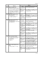
Replace the main charger unit (see page 1-6-40).
Clean the main charger wire, grid and shield.
Reinsert the connector. Also check for continuity within the
connector cable. If none, remedy or replace the cable.
Check if YC9-5 on the engine PCB goes low when maintenance item
U100 is run. If not, replace the engine PCB.
Check if main charging takes place when YC1-12 on the high-
voltage PCB goes low while maintenance item U100 is run. If not,
replace the high-voltage PCB.
Reinsert the connector. Also check for continuity within the
connector cable. If none, remedy or replace the cable.
Check if the exposure lamp lights when YC1-1 and 1-6 on the
inverter PCB go low while maintenance item U061 is run. If not,
replace the inverter PCB.
Check if YC17-1 and YC17-6 on the engine PCB goes low when
maintenance item U061 is run. If not, replace the engine PCB.
Summary of Contents for cd 1116
Page 1: ...Service Manual Copy CD 1116 CD 1120 Rev 1 ...
Page 2: ...Service Manual Copy DC 2116 DC 2120 Rev 1 ...
Page 4: ...This page is intentionally left blank ...
Page 247: ...2DA 2DB 1 2 3 2 Figure 2 3 2 Power source PCB silk screen diagram 220 240 V AC 120 V AC ...
Page 264: ...2DA 2DB 1 2 3 19 Figure 2 3 10 Operation unit PCB silk screen diagram ...


