2DA/2DB-1
1-6-37
Change the setting.
Increasing the value using the right
cursor key makes the margin wider.
Decreasing the value using the left
cursor key makes the margin
narrower.
Yes
No
Start
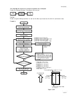
Enter maintenance mode.
Enter “403” using the numeric keys.
Press the start key.
Press the start key
to make a test copy
(A test copy is output at the
reduction ratio of 95%).
Press the start key.
The new setting
is stored.
Setting range (Initial setting)
A MARGIN: 0.0 – +10.0 (2.0)
B MARGIN: 0.0 – +10.0 (3.0)
C MARGIN: 0.0 – +10.0 (2.0)
D MARGIN: 0.0 – +10.0 (2.0)
Changing the value by 1 moves the
leading edge by 0.1 mm.
Select the items to be adjusted
using the up/down cursor keys.
Are the margins correct?
Press the interrupt key.
Yes
No
Proceed to another mode?
End
Press the stop/clear key to
exit maintenance mode.
A MARGIN: Scanner left margin
B MARGIN: Scanner leading edge margin
C MARGIN: Scanner right margin
D MARGIN: Scanner trailing edge margin
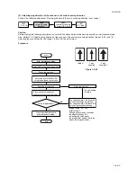
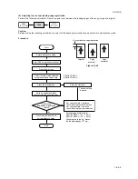
(10) Adjusting the margins for scanning an original on the contact glass
Perform the following adjustment if the margins are not correct.
U402
(P. 1-6-20)
U404
(P. 1-4-44)
U403
Caution:
Before making the following adjustment, ensure that the above adjustments have been made in maintenance mode.
Procedure
Scanner leading edge margin
(3
±
2.5 mm)
Scanner
left margin
(2.5
+1.5
mm)
Scanner
right margin
(2.5
+1.5
mm)
Ejection direction
(reference)
Scanner trailing edge margin
(3
±
2.5 mm)
–2.0
–2.0
Figure 1-6-68
Summary of Contents for cd 1116
Page 1: ...Service Manual Copy CD 1116 CD 1120 Rev 1 ...
Page 2: ...Service Manual Copy DC 2116 DC 2120 Rev 1 ...
Page 4: ...This page is intentionally left blank ...
Page 247: ...2DA 2DB 1 2 3 2 Figure 2 3 2 Power source PCB silk screen diagram 220 240 V AC 120 V AC ...
Page 264: ...2DA 2DB 1 2 3 19 Figure 2 3 10 Operation unit PCB silk screen diagram ...

