2DA/2DB
2-1-12
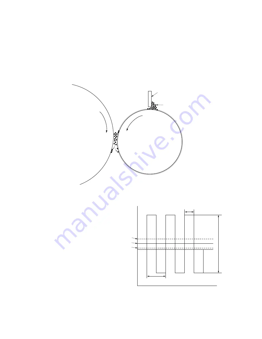
(2) Single component developing system
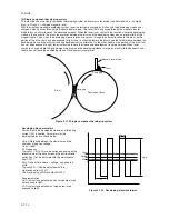
This machine uses the single component developing system, and reversal processing is performed with a + charged
drum (a-Si) and a + charged magnetic toner.
With the single component developing system, toner is electrically charged by friction with the developing sleeve and +
charged when it passes through the magnetic doctor blade. The toner that has passed through the magnetic doctor
blade forms a uniform layer on the developing sleeve. When the toner layer comes to the location where the developing
sleeve is the nearest to the drum, toner moves between the drum and the developing sleeve by an electric field of the
magnetic pole. Then, when the developing sleeve rotates and passes through the nearest location to the drum, on the
portion of the drum that has been exposed to light, toner is attracted toward the drum by potential difference between the
developing bias and the drum surface and development is performed. On the other hand, on the portion of the drum that
has not been exposed to light, toner is attracted toward the sleeve and development is not performed. When toner
comes to an area where the gap between the drum and the developing sleeve is large, an electric field disappears and
toner does not leave the developing sleeve. Development is complete.
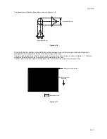
North pole
South pole
Developing sleeve
Drum
Magnetic toner blade
Toner
Figure 2-1-13 Single component developing system
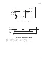
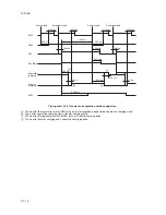
Developing bias parameters
For the bias to the developing sleeve, an alternating
current (AC) is applied. Parameters for the
developing bias are shown below.
Vp-p: Difference between the maximum and the
minimum of applied voltage
1.6 kV (fixed)
Vf: Frequency
Typically
2.7 kHz. This value varies depending on the
preset value of the drive time and the environmental
correction. (Can be adjusted with the maintenance
item U101.)
Duty: Ratio of time where + voltage is applied in a
cycle
Typically 45%. (Can be adjusted with the
maintenance item U101.)
Vdc: Developing shift bias potential 290 V
Supplementation
Vo: Drum surface potential on non-image area (area
not exposed to light)
VL: Drum surface potential on image area (area
exposed to light)
Vdc
Vo
Duty
Vf
Vp-p
VL
0
V
Figure 2-1-14 Developing bias waveformsa
Summary of Contents for cd 1116
Page 1: ...Service Manual Copy CD 1116 CD 1120 Rev 1 ...
Page 2: ...Service Manual Copy DC 2116 DC 2120 Rev 1 ...
Page 4: ...This page is intentionally left blank ...
Page 247: ...2DA 2DB 1 2 3 2 Figure 2 3 2 Power source PCB silk screen diagram 220 240 V AC 120 V AC ...
Page 264: ...2DA 2DB 1 2 3 19 Figure 2 3 10 Operation unit PCB silk screen diagram ...


