2DA/2DB-1
2-3-1
2-3-1 Power source PCB
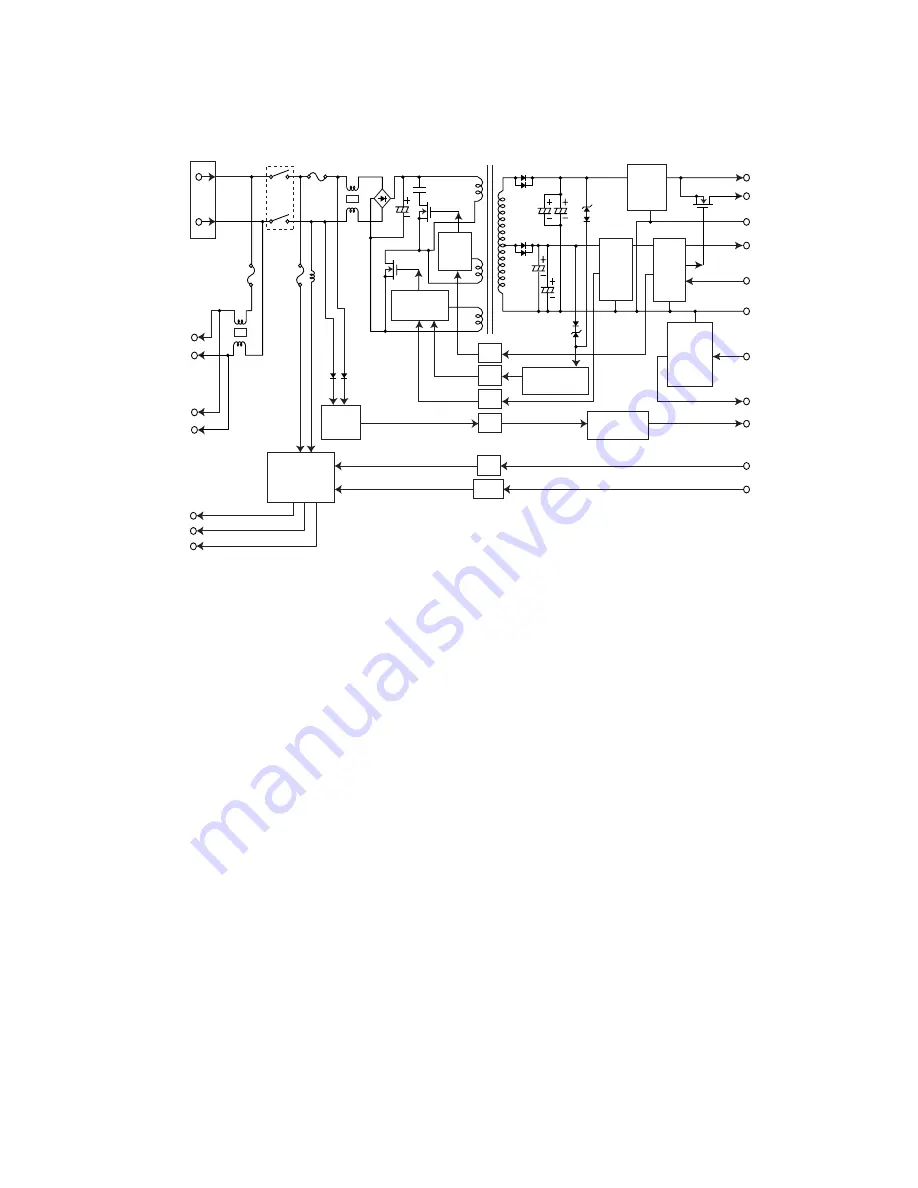
Figure 2-3-1
Power source PCB block diagram
The power source PCB (PSPCB) is a switching regulator that converts an AC input to generate 24 V DC and 5 V DC. It
includes a rectifier circuit, a switching regulator circuit, a 24 V DC output circuit, a 5 V DC output circuit, overvoltage
detection circuit, zero-cross circuit and a fixing heater control circuit.
The rectifier circuit full-wave rectifies the AC input using the diode bridge D1. The smoothing capacitor (C5) smoothes out
the pulsed current from the diode bridge.
In the switching control circuit, switching circuit turns the power MOSFET (Q1) on and off to switch the voltage induced in
the primary coil of the transformer (T1).
The 5 V DC output circuit rectifies and smoothes the voltage induced in the secondary coil of the transformer (T1) via diodes
(D102) and smoothing capacitors (C102, C105), and the output is controlled by the overvoltage detection circuit (IC101).
For 5 V DC output, the switching circuit of the switching control circuit changes the duty of the switching pulse width of the
power MOSFET (Q1) via a photo coupler (PC1) based on the output voltage status to adjust the 5 V DC output.
The 24 V DC output circuit rectifies and smoothes the voltage induced in the secondary coil of the transformer (T1) via
diodes (D101) and smoothing capacitors (C101, C104), and the output is controlled by the overvoltage detection circuit
(IC101).
The zero-cross circuit detects zero-crossing of the AC input voltage with the AC detection circuit and outputs the zero-cross
signal (ZCROSSC) from the zero-cross output circuit through the photo coupler (PC3).
The fixing heater control circuit is divided into the sub-heater output (SH.OUT) and the main heater output (MH.OUT). When
the control signals (SHEATN and MHEATN) input from the machine engine side show a low level, this circuit turns on the
sub-heater and the main heater respectively by turning on the photo triac couplers (PC2 and PC201) with a zero-cross
circuit to turn on the triacs (TRA1 and TR201) in the fixing heater ON/OFF circuit.
The power-saving control circuit performs power-saving control by turning off the 24 V DC output in the 24 V DC output ON/
OFF switching circuit and controlling the switching control circuit and the AC detection circuit through the photo coupler
(PC4) to decrease the switching frequency, stop the starting circuit in the switching control circuit, and stop the AC detection
circuit when the sleep signal (SLEPN) input from the machine engine side is low.
In addition, 5 V DC 3-terminal regulator (IC102) is connected to the back of the 24 V DC output ON/OFF switching circuit to
5 V1, and this output stops when the sleep signal (SLEPN) is low.
AC
INPUT
Zero-cross circuit
Rectifier circuit
CN1
DH1.LIVE
DH2.LIVE
DH1.OUT
DH2.OUT
SH.OUT
H.LIVE
MH.OUT
(TRA1,TR201)
D101
Q151
D1
D30
D109
D104
D111
D110
D33
T1
L2
L4
L3
L1
F1
F2
F3
Power switch
C101
C104
C5
C102
C105
Q1
Q2
D206
+24V
GND
GND
+5V
ZCROSSC
SHEATN
MHEATN
SLEPN
+24V1
+24V2
+5V1
Q153
Q154
IC101
PC1
PC5
PC4
PC3
PC2
PC201
24 V DC
output
circuit
5 V DC
3-terminal
regulator
(IC301)
Fixing heater
ON/OFF circuit
Fixing heater
control circuit
Energy
save
control
circuit
Energy
save
control
circuit
Zero-cross
output circuit
Switching
control circuit
Overvoltage
detection circuit
5 V DC
output
circuit
AC
detection
circuit
Summary of Contents for cd 1116
Page 1: ...Service Manual Copy CD 1116 CD 1120 Rev 1 ...
Page 2: ...Service Manual Copy DC 2116 DC 2120 Rev 1 ...
Page 4: ...This page is intentionally left blank ...
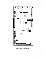
Page 247: ...2DA 2DB 1 2 3 2 Figure 2 3 2 Power source PCB silk screen diagram 220 240 V AC 120 V AC ...
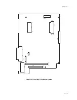
Page 264: ...2DA 2DB 1 2 3 19 Figure 2 3 10 Operation unit PCB silk screen diagram ...

