2DA/2DB-1
2-3-3
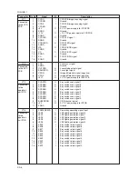
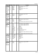
Connector
Pin No.
Signal
I/O
Description
CN1
Connected
to the AC
power plug
YC1
Connected
to the
engine PCB
and left
cover safety
switch
YC2
Connected
to the
engine PCB
YC5
Connected
to the front
cover
safety
switch
YC6
Connected
to the fixing
heater M/S
YC7
Connected
to the paper
feeder*
1
YC8
Connected
to the
drawer
heater*
2
YC9
Connected
to the paper
feeder*
1
1
AC-L
I
AC supply (LIVE)
2
FG
-
Ground
3
AC-N
I
AC supply (NEUTRAL)
1
+24V1
O
24 V DC power supply for LCSSW
2
NC
-
Not used
3
+24V2
I
24 V DC power supply (Via LCSSW)
4
+24V4
O
24 V DC power supply for EPCB (Via LCSSW)
5
PGND
-
Ground
6
SGND
-
Ground
7
+5V
O
5 V DC power supply for EPCB
1
+5V
O
5 V DC power supply for EPCB (Via FCSSW)
2
SGND
-
Ground
3
+24V2
O
24 V DC power supply (Via LCSSW)
4
SGND
-
Ground
5
ZCROSSC
O
Zero-cross signal
6
SLEPN
I
Power source sleep signal
7
SHEATN
I
FH-S on/off
8
MHEATN
I
FH-M on/off
9
COUNTN
I
Counter control signal
10
PGND
-
Ground
11
PGND
-
Ground
12
+24V1
O
24 V DC power supply for EPCB
13
+24V1
O
24 V DC power supply for EPCB
14
+24V
O
24 V DC power supply for EPCB
1
+5V1
O
5 V DC power supply for FCSSW
2
NC
-
Not used
3
+5V3
I
5 V DC power supply
1
H.LIVE
O
AC power supply for FH-M/S (LIVE)
2
MH.OUT
O
AC power supply for FH-M
3
SH.OUT
O
AC power supply for FH-S
1
DH2.LIVE
O
AC power supply for drawer heater of the paper feeder (LIVE)
2
NC
-
Not used
3
NC
-
Not used
4
DH2.OUT
O
AC power supply for drawer heater of the paper feeder
1
DH1.LIVE
O
AC power supply for drawer heater (LIVE)
2
NC
-
Not used
3
NC
-
Not used
4
DH1.OUT
O
AC power supply for drawer heater
1
+24V4
O
24 V DC power supply for paper feeder
2
PGND
-
Ground
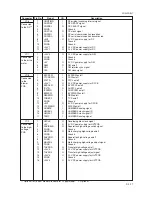
*1: Optional for 16 ppm model. Standard for 20 ppm model. *2: Optional.
Summary of Contents for cd 1116
Page 1: ...Service Manual Copy CD 1116 CD 1120 Rev 1 ...
Page 2: ...Service Manual Copy DC 2116 DC 2120 Rev 1 ...
Page 4: ...This page is intentionally left blank ...
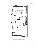
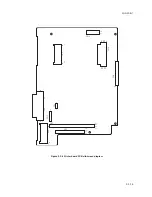
Page 247: ...2DA 2DB 1 2 3 2 Figure 2 3 2 Power source PCB silk screen diagram 220 240 V AC 120 V AC ...
Page 264: ...2DA 2DB 1 2 3 19 Figure 2 3 10 Operation unit PCB silk screen diagram ...


