1-3-14
2DA/2DB-1
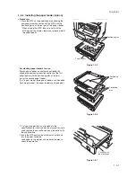
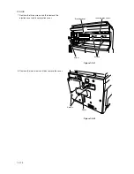
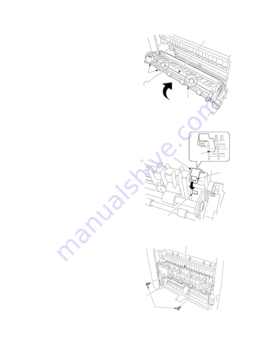
8. Press the duplex unit in the direction indicated by the
arrow to fit the claws into the conveyer unit.
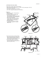
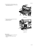
9. Hang the hook of the plate lock on the conveying unit
and then turn the plate lock to fit the hole to the claw
of the duplex unit.
10. Secure the duplex unit with the two S tite screws M3
×
06.
Figure 1-3-22-1
Figure 1-3-23
Claw
Claws
Duplex unit
Duplex unit
S tite screws
M3
×
06
Figure 1-3-22-2
Hook
Plate lock
Hole
Claw
Summary of Contents for cd 1116
Page 1: ...Service Manual Copy CD 1116 CD 1120 Rev 1 ...
Page 2: ...Service Manual Copy DC 2116 DC 2120 Rev 1 ...
Page 4: ...This page is intentionally left blank ...
Page 247: ...2DA 2DB 1 2 3 2 Figure 2 3 2 Power source PCB silk screen diagram 220 240 V AC 120 V AC ...
Page 264: ...2DA 2DB 1 2 3 19 Figure 2 3 10 Operation unit PCB silk screen diagram ...


