2DA/2DB
1-4-13
Maintenance
Description
item No.
U053
MAIN MOTOR
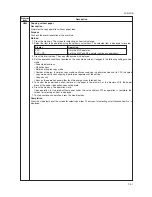
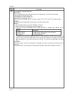
Increasing the setting makes the image longer in the auxiliary scanning direction, and decreasing it makes
the image shorter in the auxiliary scanning direction.
POLYGON MOTOR
Increasing the setting makes the image longer in the main scanning direction and shorter in the auxiliary
scanning direction; decreasing the setting makes the image shorter in the main scanning direction and
longer in the auxiliary scanning direction.
3. Press the start key. The value is set.
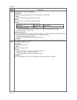
Interrupt copy mode
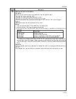
While this maintenance item is being performed, a VTC pattern shown below is output in interrupt copy mode.
1. Press the interrupt key. The machine enters the interrupt copy mode.
2. Press the start key. A VTC pattern is output.
To return to the screen for setting, press the interrupt key.
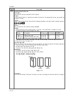
Correct values for an A3/11"
×
17" output are:
A = 300 ± 1.5 mm
B = 270 ± 1.35 mm
Figure 1-4-1
Adjustment
1. Output an A3/11"
×
17" VTC pattern in interrupt copy mode.
2. Measure A and B on the VTC pattern (Figure 1-4-1), and perform the following adjustments if they are
different from the correct sizes:
A: Drive motor speed adjustment
B: Polygon motor speed adjustment
Completion
Press the stop/clear key at the screen for setting. The screen for selecting a maintenance item No. is displayed.
Summary of Contents for cd 1116
Page 1: ...Service Manual Copy CD 1116 CD 1120 Rev 1 ...
Page 2: ...Service Manual Copy DC 2116 DC 2120 Rev 1 ...
Page 4: ...This page is intentionally left blank ...
Page 247: ...2DA 2DB 1 2 3 2 Figure 2 3 2 Power source PCB silk screen diagram 220 240 V AC 120 V AC ...
Page 264: ...2DA 2DB 1 2 3 19 Figure 2 3 10 Operation unit PCB silk screen diagram ...


