2GL/2FV/2FW
2-3-3
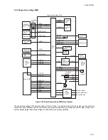
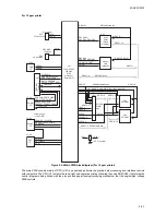
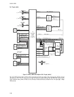
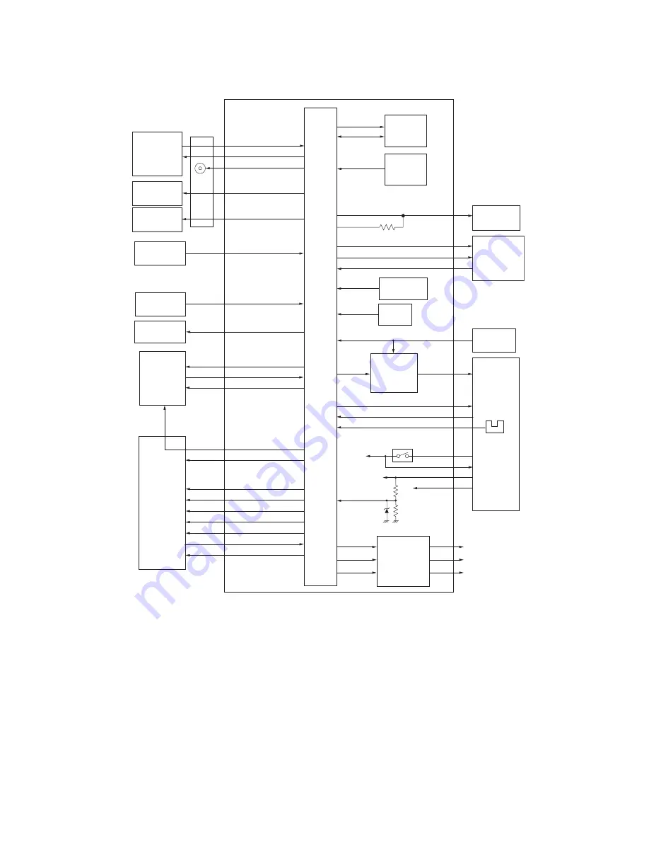
2-3-2 Engine/high voltage PWB
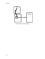
Figure 2-3-2 Engine/high voltage PWB block diagram
The engine/high voltage PWB consists mainly of CPU (U1) and it is primarily divided into the engine circuit section that
controls the entire hardware such as the process and paper feeding/conveying mechanism and the high voltage circuit
section that generates various high voltages to output during the process operation.
EE
D
IO
EECLK
RESETN
EEPROM
(U2)
Reset IC
(U3)
TN
F
ULL
TONER
ERASERON
F
ANH
F
ANL
MMOTON
MOTCLK
MMOTR
D
Y
Z
CROSS
SLEEPN
HEATN
HEAT
THERM
EXITPAP
ILOCK
ILOCK
Main char
g
er
24V2
Exit
sensor
5V
D
e
v
elopin
g
b
ias
Transfer
b
ias
24V2
24V1
24V1
Coolin
g
fan
motor
Main motor
Main PWB
F
user
thermistor
Power
source
PWB
PL
G
ON
PL
G
R
D
Y
Interloc
k
switch
F
PSW
En
g
ine/hi
g
h
v
olta
g
e PWB
F
PLE
D
1,
F
PLE
D
2
BU
ZZ
Buzzer
RE
G
SOLON
F
E
D
SOLON
PL
G
CLK
OUTPEN
Operation
panel PWB
Connect
PWB
Re
g
istration
clutch
F
ee
d
clutch
Paper
sensor
Re
g
istration
sensor
RESETN
PL
G
CLK
E
G
IRN
S
D
IR
SBSY
P
D
MASKN
E
G
SI
E
G
SO
CPU
(U1)
Hi
g
h
v
olta
g
e
circuit
F
user
temperature
a
b
normal
circuit
Toner empty
sensor
Waste toner
full sensor
Eraser lamp
PWB
Laser
scanner
unit
Summary of Contents for LP 3118
Page 1: ...Service Manual Printer LP 3118 22 02 2005 ...
Page 2: ...Service Manual Printer LP 4118 22 02 2005 ...
Page 7: ...This page is intentionally left blank ...
Page 19: ...2GL 2FV 2FW 1 1 10 This page is intentionally left blank ...
Page 21: ...2GL 2FV 2FW 1 2 2 This page is intentionally left blank ...
Page 29: ...2GL 2FV 2FW 1 3 8 This page is intentionally left blank ...
Page 41: ...2GL 2FV 2FW 1 4 12 This page is intentionally left blank ...
Page 65: ...2GL 2FV 2FW 1 5 24 This page is intentionally left blank ...
Page 95: ...2GL 2FV 2FW 1 7 6 This page is intentionally left blank ...
Page 125: ...2GL 2FV 2FW 2 4 6 This page is intentionally left blank ...
Page 126: ......

