2GL/2FV/2FW
1-3-5
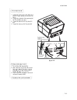
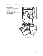
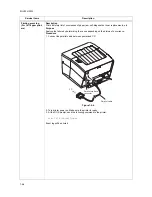
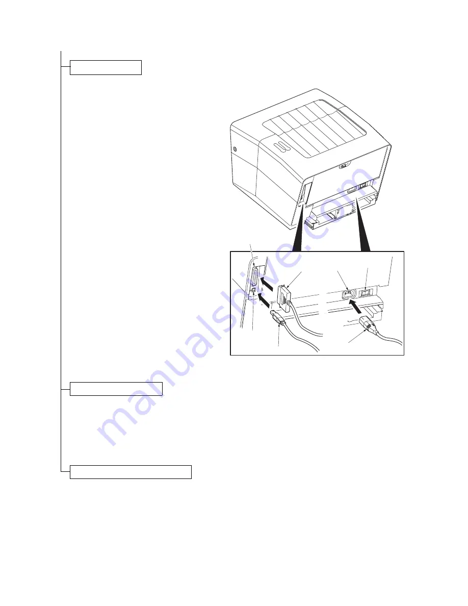
1. Connect the printer cable to the USB or par-
allel (16/18 ppm printers only) interface con-
nector.
2. Connect the other end of the printer cable to
the PC’s interface connector.
3. Connect the power cord to the printer AC
inlet.
4. Connect the power cord to the wall outlet.
Figure 1-3-7
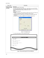
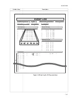
1. Turn on the printer power switch.
2. Press the GO key for 10 seconds or more.
Test page (16 ppm GDI printer) or service
status page (16/18 ppm printers) will be
printed. See page 1-4-11 or 1-4-3.
3. Check to see if the test page or service sta-
tus page is properly printed.
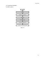
Connecting the cable.
Parallel interface
connector
(16/18 ppm printers only)
Parallel cable
AC inlet
Power switch
USB interface
connector
USB cable
Power cord
Printing a status page for test.
Completion of the machine installation.
Summary of Contents for LP 3118
Page 1: ...Service Manual Printer LP 3118 22 02 2005 ...
Page 2: ...Service Manual Printer LP 4118 22 02 2005 ...
Page 7: ...This page is intentionally left blank ...
Page 19: ...2GL 2FV 2FW 1 1 10 This page is intentionally left blank ...
Page 21: ...2GL 2FV 2FW 1 2 2 This page is intentionally left blank ...
Page 29: ...2GL 2FV 2FW 1 3 8 This page is intentionally left blank ...
Page 41: ...2GL 2FV 2FW 1 4 12 This page is intentionally left blank ...
Page 65: ...2GL 2FV 2FW 1 5 24 This page is intentionally left blank ...
Page 95: ...2GL 2FV 2FW 1 7 6 This page is intentionally left blank ...
Page 125: ...2GL 2FV 2FW 2 4 6 This page is intentionally left blank ...
Page 126: ......


